Laser waterfowl repellent

a technology of laser waterfowl and spraying device, which is applied in the field of laser waterfowl repellent, can solve the problems of not being chemical methods are useless when trying, and employing a device in a residential neighborhood that emits large blasts of sound is not the most neighborly thing to do, and is expensive to obtain and car

Inactive Publication Date: 2009-03-24
SPIEGEL H JAY
View PDF7 Cites 20 Cited by
  • Summary
  • Abstract
  • Description
  • Claims
  • Application Information

AI Technical Summary

Benefits of technology

[0020](7) Additionally, if desired, a plurality of laser beams may be provided, either through one beam that is split or through the use of a plurality of individual beams and they may be arranged in any one of a number of patterns such as (a) all at the same elevation, (b) at ascending and descending consecutive elevations, (c) in a cross configuration, or any other desired pattern. In this way, full coverage of the entire area to be protected and at elevations assuring visibility to the waterfowl will occur.

Problems solved by technology

However, they are often a nuisance when they “graze” on one's yard, particularly, when they leave large deposits of feces behind.
Such chemicals are useless when trying to keep waterfowl off a dock, pier or other non-grassy area.
However, employing a device in a residential neighborhood that emits large blasts of sound is not the most neighborly thing to do.
Animals such as border collies are also employed, but it is expensive to obtain and care for them.
It is also known that devices such as fake owls, inflatable balloons and fake inflatable snakes only deter waterfowl for short periods of time unless they are continually moved to different locations and orientations.
Such a device, while generally effective, requires the presence of the user manipulating it.
During these hours, it is often inconvenient for a property owner to use a hand-held device to disperse the waterfowl.

Method used


Image

  • Laser waterfowl repellent
  • Laser waterfowl repellent
  • Laser waterfowl repellent

Examples


Embodiment Construction

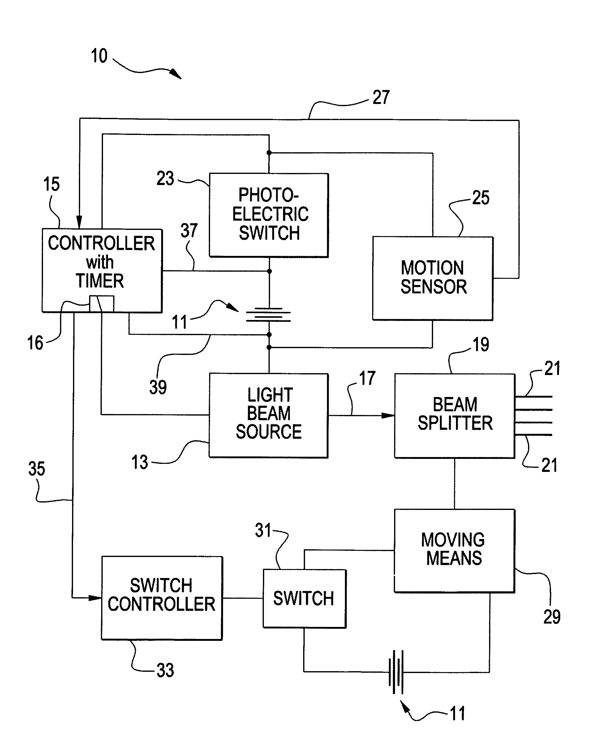
[0039]Reference is first made to FIG. 1 which shows a schematic representation of the electrical circuitry of the present invention. The circuitry is generally designated by the reference numeral 10 and is seen to include a source of power 11 which may, if desired, be 12 volt DC power, a light beam source 13, and a controller with timer 15. The light beam source may be a source of laser light or other concentrated light beam.

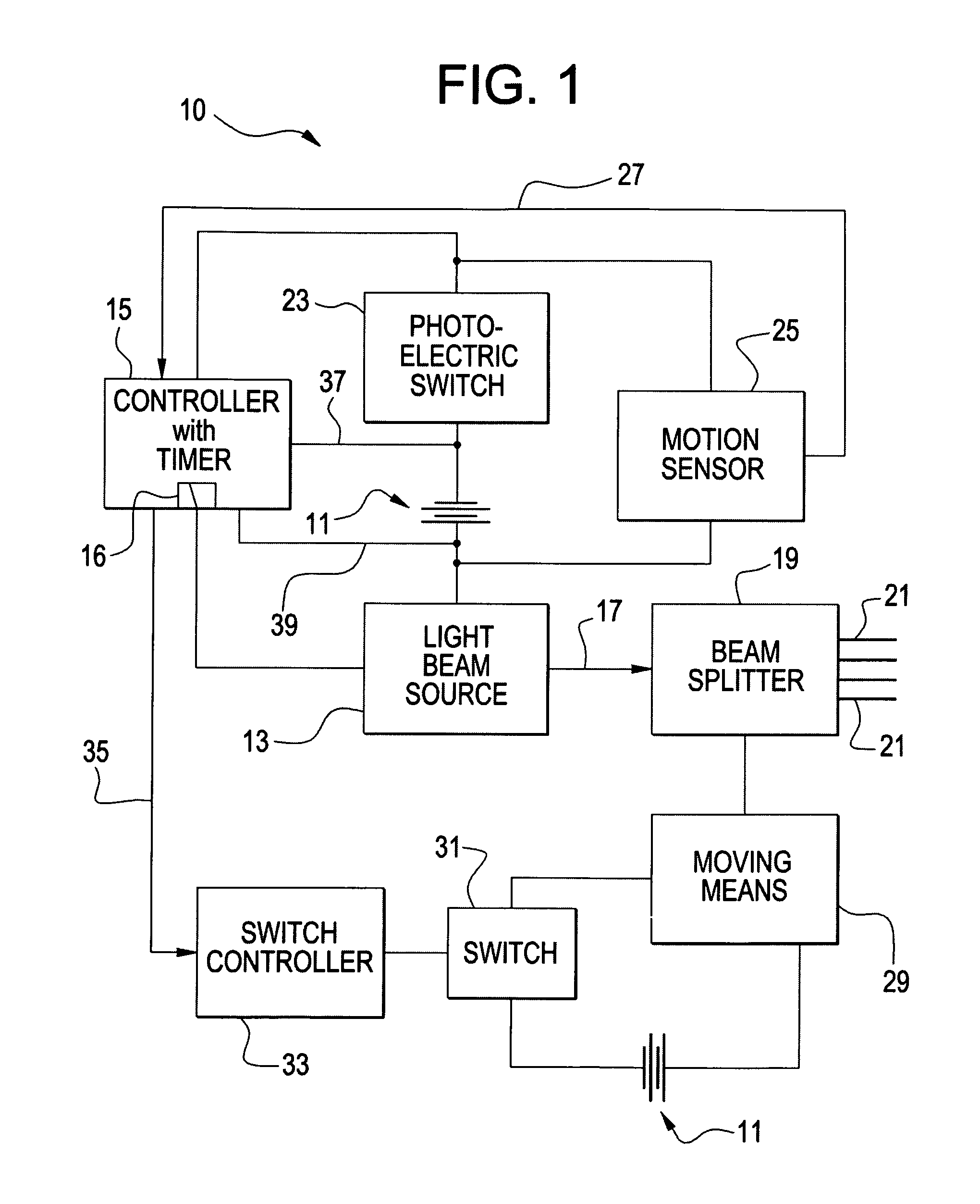
[0040]As seen in FIG. 1, a light beam 17 is emitted from the light beam source 13 and enters a beam splitter 19 where it is split into a plurality of beams 21. The beams 21, emitted by the beam splitter 19, are aimed within a region or space where it is desired to disperse and repel nuisance waterfowl.

[0041]The prime time of day when nuisance waterfowl are at their worst is typically from dusk until dawn. As such, a photoelectric switch 23 is provided in the circuitry 10. The photoelectric switch senses the dimming of light at dusk and the restoration of light a...


PUM


Abstract

A device to repel and disperse waterfowl entering a proscribed area consists of a laser beam generator generating a laser beam, and a photoelectric switch is provided so that the inventive device is only activated from dusk to dawn. A motion sensor senses the presence of waterfowl and activates the light beam source that is aimed into the area. In the preferred embodiment, a timer is provided that may be set for a desired duration. When the desired duration has elapsed, the controller deactivates the light beam source. The light beam source may consist of a single laser beam or a multiplicity of laser beams shining into the protected area. In one preferred embodiment of the present invention, a single laser beam is split into a plurality or multiplicity of beams using a suitable beam splitter. The inventive device may be equipped with a system that enables one or more laser beams to sweep and oscillate through the protected area so that not only is full coverage of the area assured, but the elevation of the beams is at least, at some points in time, at the level of the eyes of the waterfowl so that the waterfowl can detect the presence of the laser beams and quickly flee the area.

Description

BACKGROUND OF THE INVENTION[0001]The present invention relates to a laser waterfowl repellent. Waterfowl such as geese and ducks are beautiful to observe from a distance. However, they are often a nuisance when they “graze” on one's yard, particularly, when they leave large deposits of feces behind. Geese, in particular, are stubborn animals. If they are chased away, more often than not, they will return over and over again. Studies have shown that migratory waterfowl are responsible for international spread of Avian flu. As such, it has become important to avoid contact with these wild animals.[0002]Even in this day and age, solutions to the problems of nuisance waterfowl are few and far between. Chemical repellents are often used in grassy areas to make the grass unpalatable for eating waterfowl. Such chemicals are useless when trying to keep waterfowl off a dock, pier or other non-grassy area.[0003]Noisemakers are often used, particularly at airports, to control when large waterf...

Claims


Application Information

Patent Timeline
Patent Type & Authority Patents(United States)
IPC IPC(8): A01K37/00A01M31/00
CPCA01M29/10A01M31/002
Inventor SPIEGEL, H. JAY
Owner SPIEGEL H JAY
Why Eureka
Try Eureka