Multiple yarn delivery to a single needle method and apparatus

a single needle and yarn technology, applied in the field of textile machinery, can solve the problems of limited pattern potential, inconvenient and time-consuming cable connection, and inconfigurable use of creels shown and described in these patents

Inactive Publication Date: 2009-03-24
MILLIKEN & CO
View PDF6 Cites 26 Cited by
  • Summary
  • Abstract
  • Description
  • Claims
  • Application Information

AI Technical Summary

Problems solved by technology

Cabling is therefore believed to be inconvenient and time consuming.
Magazining, on the other hand, would appear to limit to two the number of yarn strands capable of being used and thus limits the pattern potential.
However, the creels shown and described in these patents are not configured to be utilized with beams of yarn.

Method used


Image

  • Multiple yarn delivery to a single needle method and apparatus
  • Multiple yarn delivery to a single needle method and apparatus
  • Multiple yarn delivery to a single needle method and apparatus

Examples


Embodiment Construction

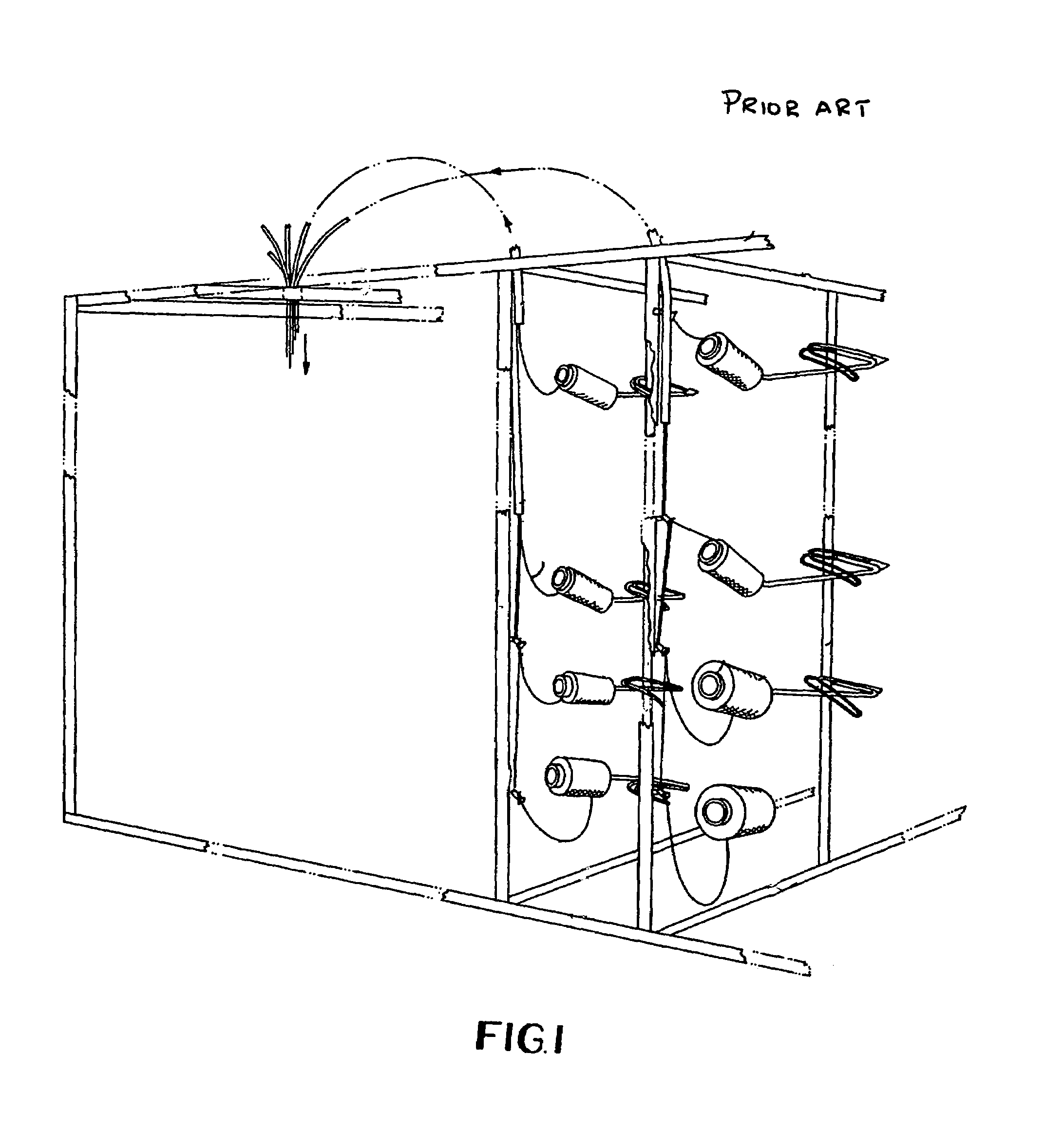
[0014]FIG. 1 is a prior art creel taken from U.S. Pat. No. 5,531,392. The yarn cones direct yarns into eyelets or into tubes at a creel. The specific yarns which will be directed to a single needle are placed together at the creel.

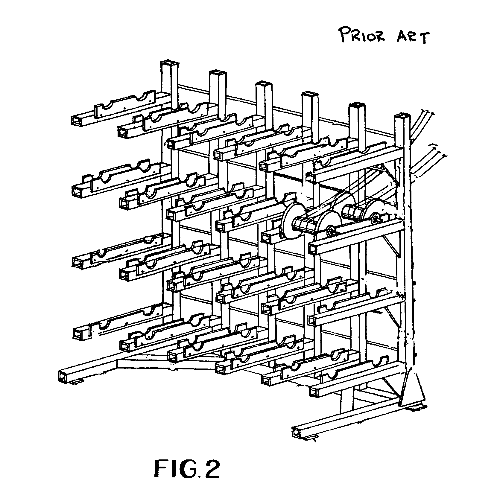
[0015]FIG. 2 is a prior art beam system taken from U.S. Pat. No. 6,592,069. While each beam has a plurality of yarn ends wrapped thereabout, each yarn end is directed to a separate needle.

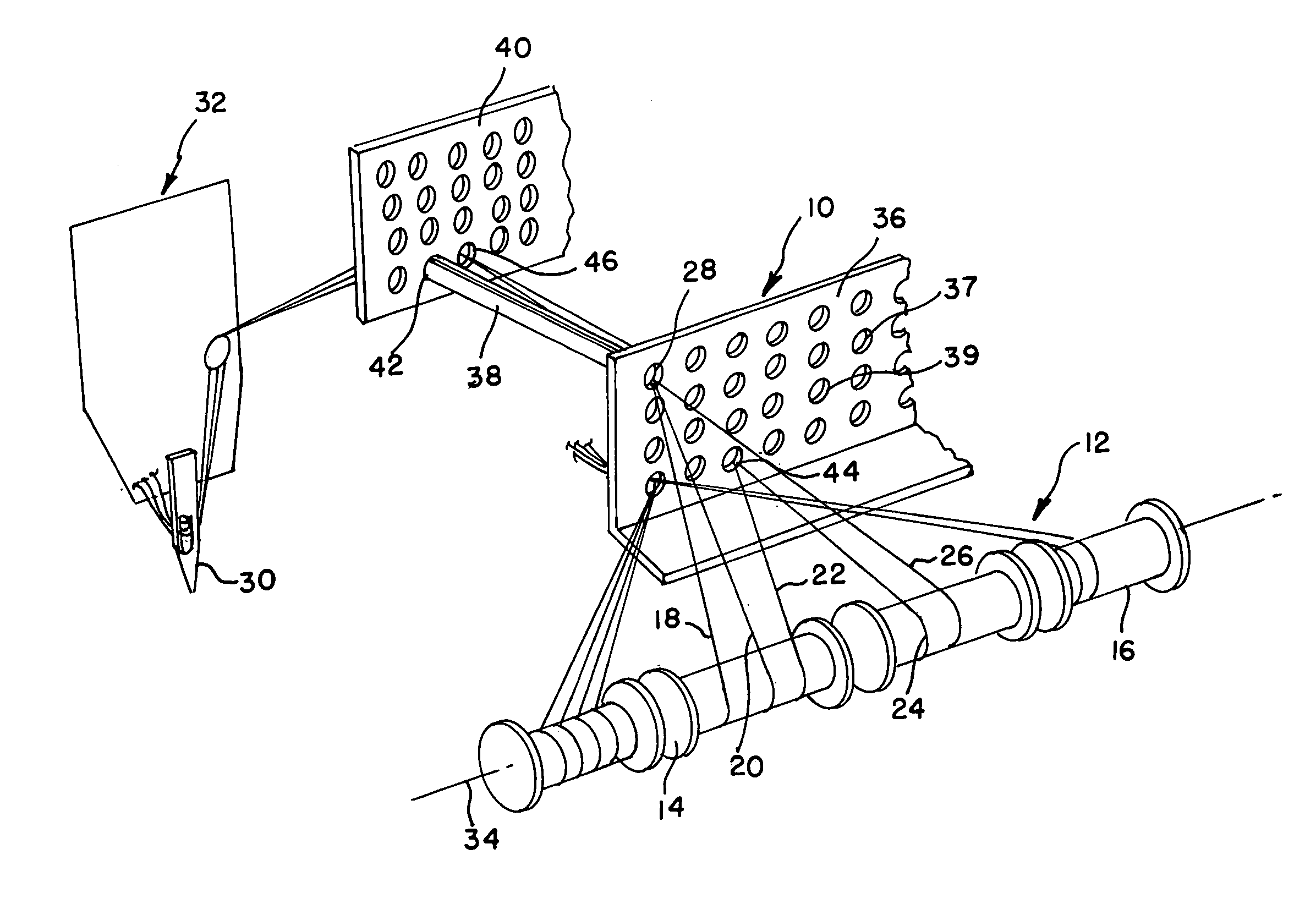
[0016]FIG. 3 shows the presently preferred embodiment of the present invention having a header 10 connected to a yarn supply 12. The yarn supply 12 is illustrated as having a plurality of beams 14. Each of the beams 14,16 is preferably wound with at least two, and possibly three or more yarn ends 18,20,22 and 24,26. From the yarn supply, the yarn ends 18,20,22 and 24,26 are directed to the header 12 without inserting the yarn ends 18,20,22 directly into guide tubes as is done in with the creel configurations shown in U.S. Pat. Nos. 5,531,392 and 5,613,643.

[0017]At the hea...


PUM

PropertyMeasurementUnit
axis of rotationaaaaaaaaaa
rotationaaaaaaaaaa
axes of rotationaaaaaaaaaa

Abstract

A textile machine receives a plurality of yarn strands from a yarn supply. A header receives the yarn strands where multiple strands are combined for joint direction to the textile machine. Beams with multiple yarn strands wrapped thereon preferably function as the yarn supply and the header may direct through yarn tubes to a staging header for use by the textile machine. The textile machine is preferably a tufting machine and multiple yarn strands are received by at least one needle of the tufting machine.

Description

BACKGROUND OF THE INVENTION[0001]This invention relates to textile machinery and its use, and more particularly to textile manufacturing machines such as a creel wherein a group of a plurality of yarn strands are received and are fed to the textile machinery.DESCRIPTION OF RELATED ART[0002]In textile machines, such as tufting machines, yarn is normally fed to the machinery either directly from a creel or from a warper. A creel is a frame having an array of vertical and horizontal support members including a multiplicity of yarn cone holders. A yarn cone is a spool about which yarn is wound. There are a multiplicity of yarn cone holders provided in horizontally and vertically disposed pairs, one cone holder of the pair mounting the active yarn cone and the other mounting a reserve or magazine cone used after the active cone is emptied. Each cone holder pair normally has its own yarn guide tube through which yarn on each holder of the pair may be fed. While this is the standard arrang...

Claims


Application Information

Patent Timeline
Patent Type & Authority Patents(United States)
IPC IPC(8): D02H1/00
CPCB65H49/16B65H49/32B65H51/015B65H57/12B65H57/16D02H1/00D05C15/18B65H2701/31
Inventor WEINER, ROBERT S.
Owner MILLIKEN & CO
Why Eureka
Try Eureka