Image forming apparatus

a technology of forming apparatus and forming tube, which is applied in the direction of electrographic process apparatus, instruments, printing, etc., can solve the problems of marked decline in image quality

Inactive Publication Date: 2009-03-24
FUJIFILM CORP
View PDF14 Cites 11 Cited by
  • Summary
  • Abstract
  • Description
  • Claims
  • Application Information

AI Technical Summary

Benefits of technology

[0010]The present invention has been contrived in view of the foregoing circumstances, an object thereof being to provide an image forming apparatus which forms desirable images free of unevenness, color mixing, or the like, by causing a liquid having electrorheological properties situated on a medium to display electrorheological properties reliably, thereby preventing deposition interference involving coalescence of mutually adjacent liquid droplets on the ejection receiving medium, displacement of the dot forming positions from the prescribed landing positions, or disturbance of the dot shapes.

Problems solved by technology

If streaks, non-uniformities, or the like, occur, and color mixing arises whereby the inks of different colors mix together on the medium when a color image is formed, then the image quality declines markedly.

Method used


Image

  • Image forming apparatus
  • Image forming apparatus
  • Image forming apparatus

Examples


first embodiment

General Composition of Inkjet Recording Apparatus

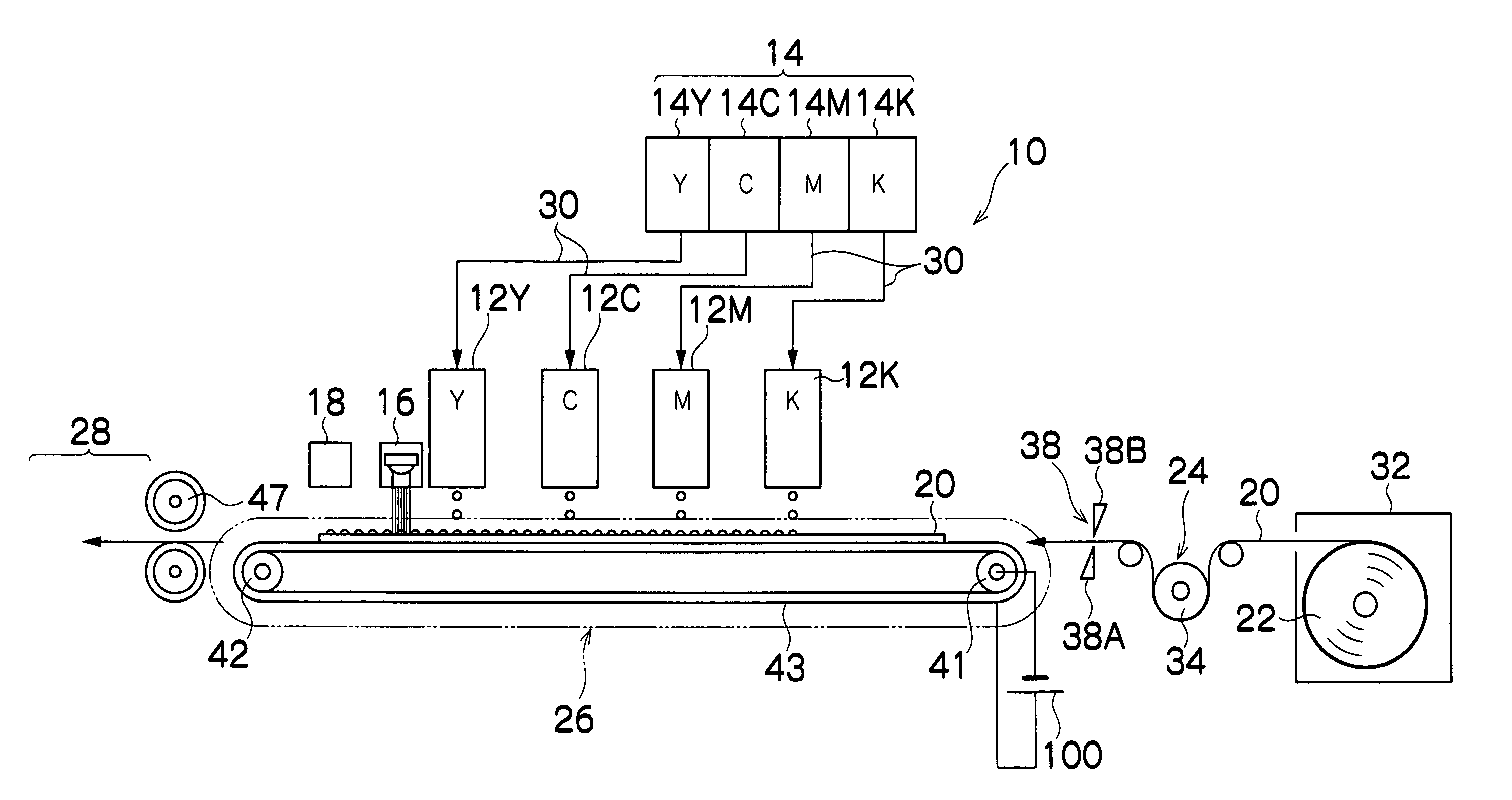
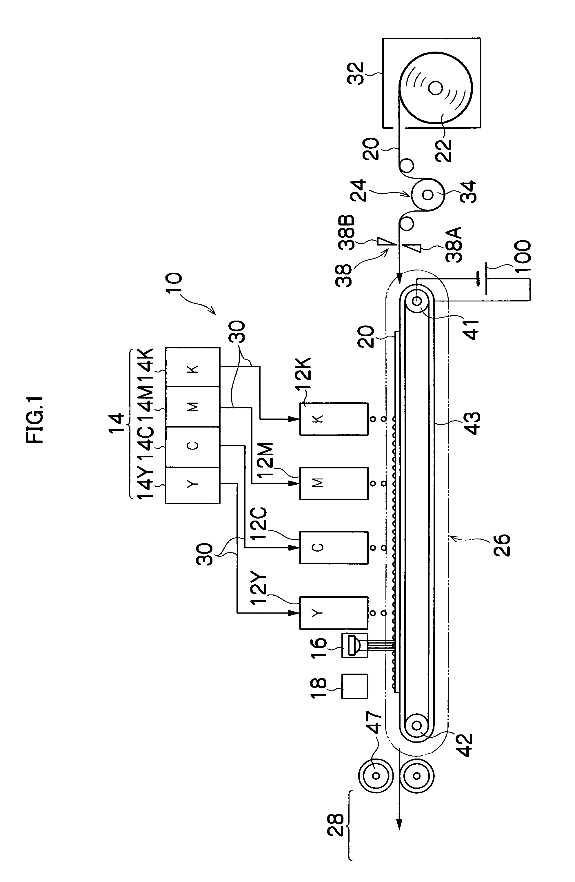
[0067]FIG. 1 is a diagram of the general composition of an inkjet recording apparatus according to a first embodiment of the present invention. As shown in FIG. 1, the inkjet recording apparatus 10 comprises: a plurality of print heads 12K, 12M, 12C, and 12Y provided corresponding to the respective ink colors of black (K), magenta (M), cyan (C) and yellow (Y); an ink storing and loading unit 14 for storing inks (in the present embodiment, ultraviolet-curable inks having electrorheological properties) to be supplied to the print heads 12K, 12M, 12C, and 12Y; an ultraviolet light source 16 which solidifies ink droplets by irradiating ultraviolet light onto same; a print determination unit 18 for reading the printed results produced by the print heads 12K, 12M, 12C, and 12Y; a paper supply unit 22 for supplying recording paper (ejection receiving medium) 20; a decurling unit 24 for removing curl in the recording paper 20; a paper conveya...

second embodiment

Structure of Belt-Type Electrode Unit

[0166]Next, a second embodiment of the present invention will be described. In the diagram illustrating the second embodiment, those parts which are the same or similar to those in the diagram illustrating the first embodiment are labeled with the same reference numerals, and description thereof is omitted.

[0167]FIG. 12 is a plan view perspective diagram showing the structure of a belt-type electrode unit 200 according to the second embodiment. The belt type electrode unit 200 comprises, in addition to the composition of the belt-type electrode unit 43 according to the first embodiment, a second electrode group 202 having a comb-shaped section in the main scanning direction, which is substantially perpendicular to the first electrode group 120.

[0168]When a prescribed voltage is applied to the second electrode group 202 by the DC high-voltage generator 100, an electric field is formed in a direction substantially parallel to the sub-scanning direc...

modification example

[0209]FIG. 18 shows an inkjet recording apparatus 300 according to a modification example of the first and second embodiments described above. FIG. 18 shows the principal part of an inkjet recording apparatus 300, and a portion of the composition of the inkjet recording apparatus 10 shown in FIG. 1 is omitted. Further, items which are the same as or similar to those in FIG. 1 are denoted with the same reference numerals and description thereof is omitted here.

[0210]The inkjet recording apparatus 300 shown in FIG. 18 comprises a roller-type electrode unit 302, instead of the belt type electrode unit 43 of the inkjet recording apparatus 10 shown in FIG. 1. The print heads 12K, 12M, 12C, and 12Y are disposed in sequence from the upstream side toward the downstream side in the direction of rotation of the roller type electrode unit 302, and the ultraviolet light source 16 is provided on the downstream side of the print head 12Y. A nip roller 310 which functions as a guide for directing ...


PUM


Abstract

The image forming apparatus comprises: an ejection head which forms an image on an ejection receiving medium, by ejecting liquid having electrorheological properties onto the ejection receiving medium; a holding device which holds the ejection receiving medium on a surface facing a liquid ejection surface of the ejection head; a conveyance device which conveys at least one of the ejection head and the ejection receiving medium held by the holding device relatively to each other in a conveyance direction; a first electrode group which includes at least a pair of a positive electrode and a negative electrode provided in the holding device, has a lengthwise direction coinciding with a sub-scanning direction substantially parallel to the conveyance direction of the conveyance device, and is disposed so as to be aligned with the main scanning direction substantially perpendicular to the sub-scanning direction; and a voltage supply device which supplies a prescribed voltage to the first electrode group.

Description

BACKGROUND OF THE INVENTION[0001]1. Field of the Invention[0002]The present invention relates to an image forming apparatus, and more particularly, to image forming technology in an image forming apparatus using liquid which exhibits electrorheological properties.[0003]2. Description of the Related Art[0004]In recent years, inkjet recording apparatuses have come to be used widely as data output apparatuses for outputting images, documents, or the like. By driving nozzles provided in a print head in accordance with data, an inkjet recording apparatus is able to form data onto a recording medium, such as recording paper, by means of ink ejected from the nozzles.[0005]If streaks, non-uniformities, or the like, occur, and color mixing arises whereby the inks of different colors mix together on the medium when a color image is formed, then the image quality declines markedly. In order to reduce decline in the quality of the print image, a method has been proposed in which an image is for...

Claims


Application Information

Patent Timeline
Patent Type & Authority Patents(United States)
IPC IPC(8): B41J2/01
CPCB41J2/04B41J2/06B41J2002/14459B41J2202/20
Inventor HIRAKAWA, TAKASHI
Owner FUJIFILM CORP
Why Eureka
Try Eureka