Master cylinder with a braking stroke simulator

a master cylinder and simulator technology, applied in the field of master cylinders, can solve the problems of insufficient to meet the requirement for minimizing the master cylinder as a whole, abnormalities cannot be detected, etc., and achieve the effect of reducing the longitudinal length of the master cylinder

Inactive Publication Date: 2005-12-27
ADVICS CO LTD
View PDF6 Cites 3 Cited by
  • Summary
  • Abstract
  • Description
  • Claims
  • Application Information

AI Technical Summary

Benefits of technology

[0008]Accordingly, it is an object of the present invention to provide a master cylinder having a braking stroke simulator used for a component of a hydraulic brake apparatus for a vehicle, which is provided with a seal member of a highly reliable cut-off property whose function can be monitored properly, and which is capable of reducing a longitudinal length of the master cylinder.

Problems solved by technology

According to the hydraulic brake apparatus as disclosed in the Japanese Patent Laid-open publication, however, even if the seal member could not act as the cut-off means sufficiently, any abnormality could not be detected as far as the pressure control device is normal.
Therefore, it is required to provide the manually operated braking member with a large stroke, when the pressure control device is abnormal.
As the stroke simulator is disposed behind the master piston according to the apparatus as disclosed in the Japanese Patent Laid-open publication, the longitudinal length of the master cylinder is made long, so that it is insufficient to fulfill the requirement for minimizing the master cylinder as a whole.

Method used


Image

  • Master cylinder with a braking stroke simulator
  • Master cylinder with a braking stroke simulator
  • Master cylinder with a braking stroke simulator

Examples


Embodiment Construction

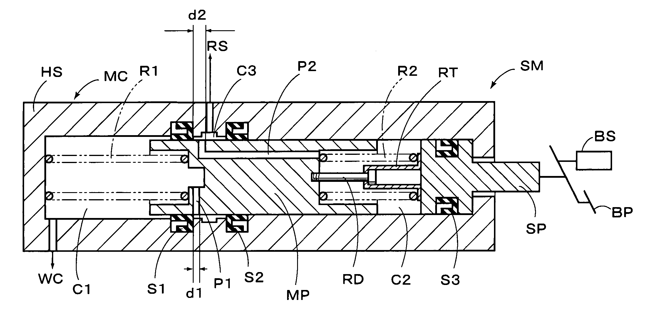
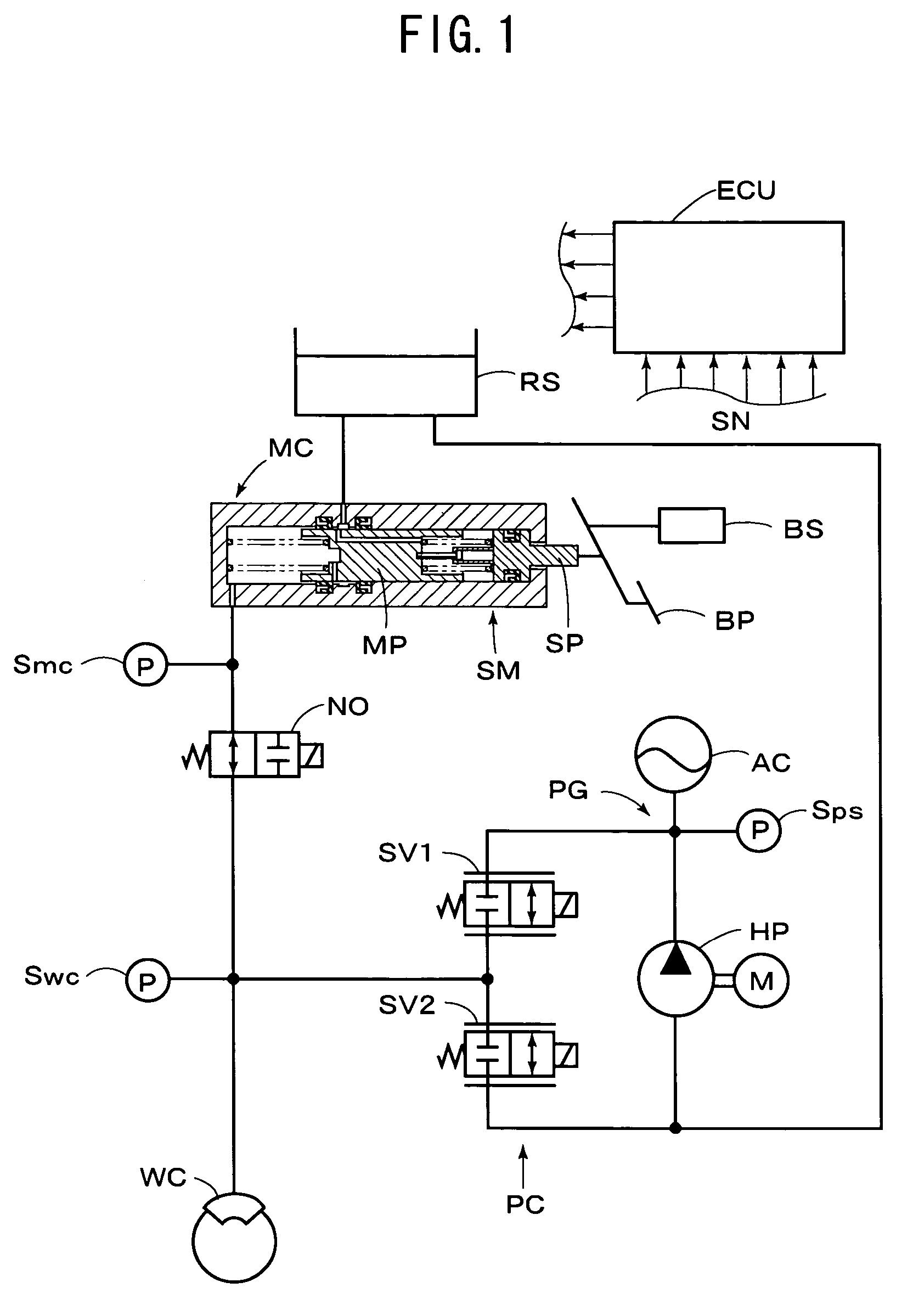
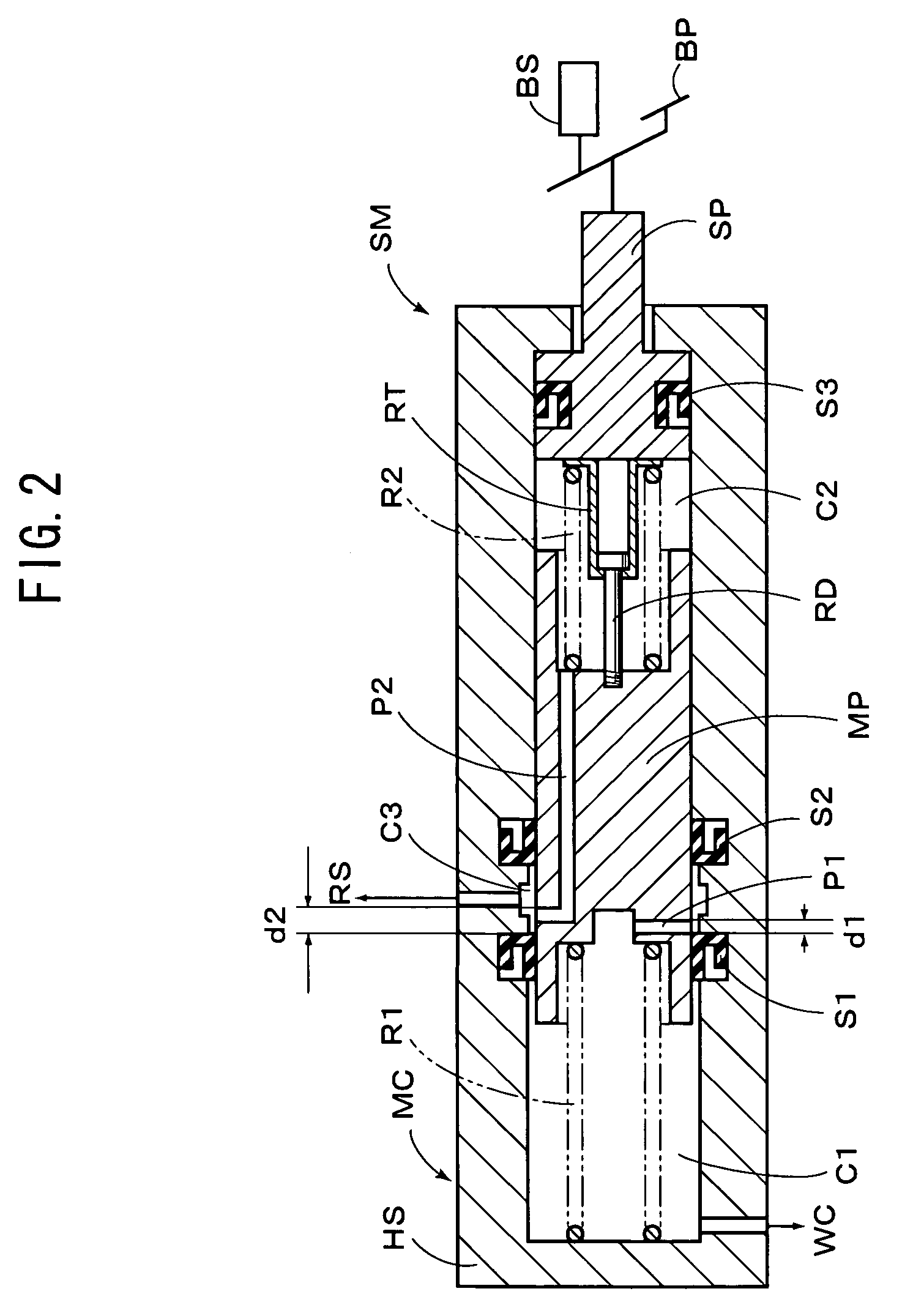
[0020]Referring to FIG. 1, there is illustrated a hydraulic brake apparatus for a vehicle having a master cylinder with a braking stroke simulator according to an embodiment of the present invention, which includes a master cylinder for generating hydraulic pressure in response to operation of a brake pedal BP, which is served as a manually operated braking member, i.e., braking operation by a vehicle driver. The apparatus includes wheel brake cylinders (indicated by WC), each of which is operatively mounted on each wheel of the vehicle, to apply braking force to the wheel with the hydraulic pressure fed from the master cylinder MC. And, a normally open electromagnetic switching valve NO is disposed between the master cylinder MC and the wheel brake cylinder WC. Furthermore, a pressure source PG for generating a certain hydraulic pressure irrespective of the braking operation of the vehicle driver is connected to a hydraulic passage between the switching valve NO and the wheel brake...


PUM


Abstract

The present invention is directed to a master cylinder having a braking stroke simulator, wherein a master piston is slidably accommodated in a housing having an atmospheric pressure chamber and a master pressure chamber, and a simulator piston is slidably accommodated in the housing to define a simulator chamber. An elastic member is provided for applying a stroke of the simulator piston in response to braking operation force applied to a manually operated braking member. Thus, the braking stroke simulator transmits the braking operation force to the master piston through the simulator piston and elastic member. A cut-off seal member is disposed in the housing for supporting the master piston, and placed to be applied with the pressure in the master pressure chamber in front of it and applied with the atmospheric pressure behind it. And, a passage is formed in the master piston to communicate the simulator chamber with the atmospheric pressure chamber when the master piston is placed in its initial position. The cut-off seal member is positioned relative to the passage to block the communication between the simulator chamber and the atmospheric pressure chamber, when the master piston is advanced by a predetermined stroke from the initial position.

Description

[0001]This application claims priority under 35 U.S.C. Sec. 119 to No. 2003-137376 filed in Japan on May 15, 2003, the entire content of which is herein incorporated by reference.BACKGROUND OF THE INVENTION[0002]1. Field of the Invention[0003]The present invention relates to a master cylinder for use in a hydraulic brake apparatus of a vehicle, and more particularly to a master cylinder with a braking stroke simulator operated in response to operation of a manually operated braking member.[0004]2. Description of the Related Arts[0005]Heretofore, there is known various hydraulic brake apparatuses each having a master cylinder with a braking stroke simulator. Among them, such an apparatus as discussed below has been disclosed in Japanese Patent Laid-open publication No. 11-59349. According to the apparatus, when a pressure control device including a pressure source is normal, the hydraulic pressure generated by the pressure source is controlled by the pressure control device in respon...

Claims


Application Information

Patent Timeline
Patent Type & Authority Patents(United States)
IPC IPC(8): B60T7/04B60T8/38B60T8/40B60T11/16
CPCB60T7/04B60T7/042B60T8/38B60T8/4081B60T11/16
Inventor KUSANO, AKIHITO
Owner ADVICS CO LTD
Why Eureka
Try Eureka