Hybrid low pass diplex filter

a diplex filter and low-pass technology, applied in the field of diplex filters, can solve the problems of return loss and increased delay

Active Publication Date: 2009-03-24
PPC BROADBAND INC
View PDF3 Cites 44 Cited by
  • Summary
  • Abstract
  • Description
  • Claims
  • Application Information

AI Technical Summary

Problems solved by technology

Using typical minimum inductor or capacitor design techniques in the lowpass leg of a diplex bandstop filter creates a problem in achieving a flat upper passband, thus causing return loss and increased delay.
In fact, the values are large enough to create multiple re-resonances in the upper passband of the highpass leg of the filter, which are undesirable.

Method used


Image

  • Hybrid low pass diplex filter
  • Hybrid low pass diplex filter
  • Hybrid low pass diplex filter

Examples


Embodiment Construction

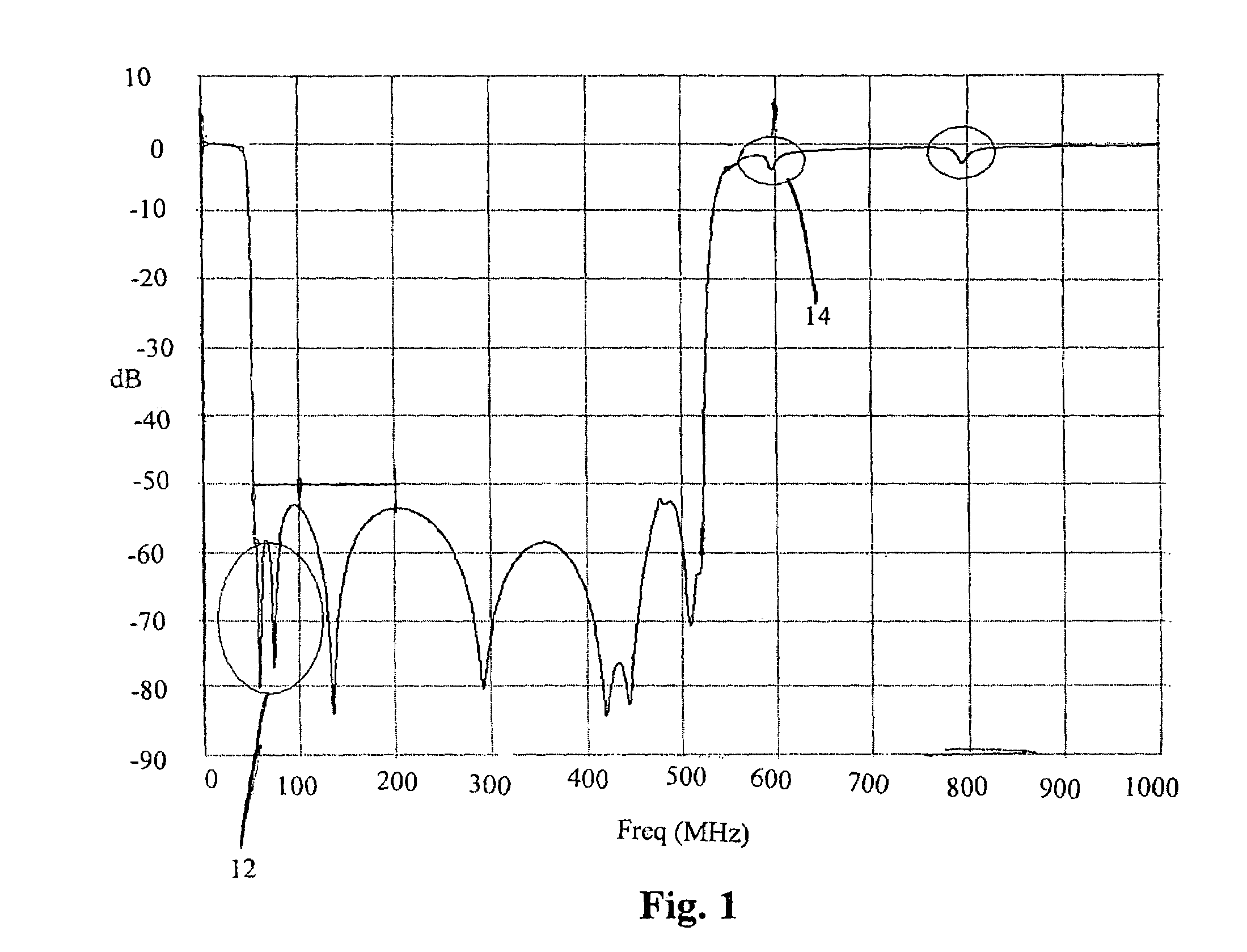
[0018]Referring to FIG. 1, the typical prior art minimum inductor or minimum capacitor design in the lowpass leg of a diplex bandstop filter creates a problem in achieving a flat upper passband, thus causing poor return loss and increased delay. This problem arises because the capacitors and coils used in combination to make the low frequency lowpass leg are extremely large in value, causing multiple re-resonances in the upper passband of the highpass leg of the filter. For example, the primary resonance at around 55.25 MHZ, as identified by reference numeral 12, causes a re-resonance at around 550 MHz as identified by reference numeral 14.

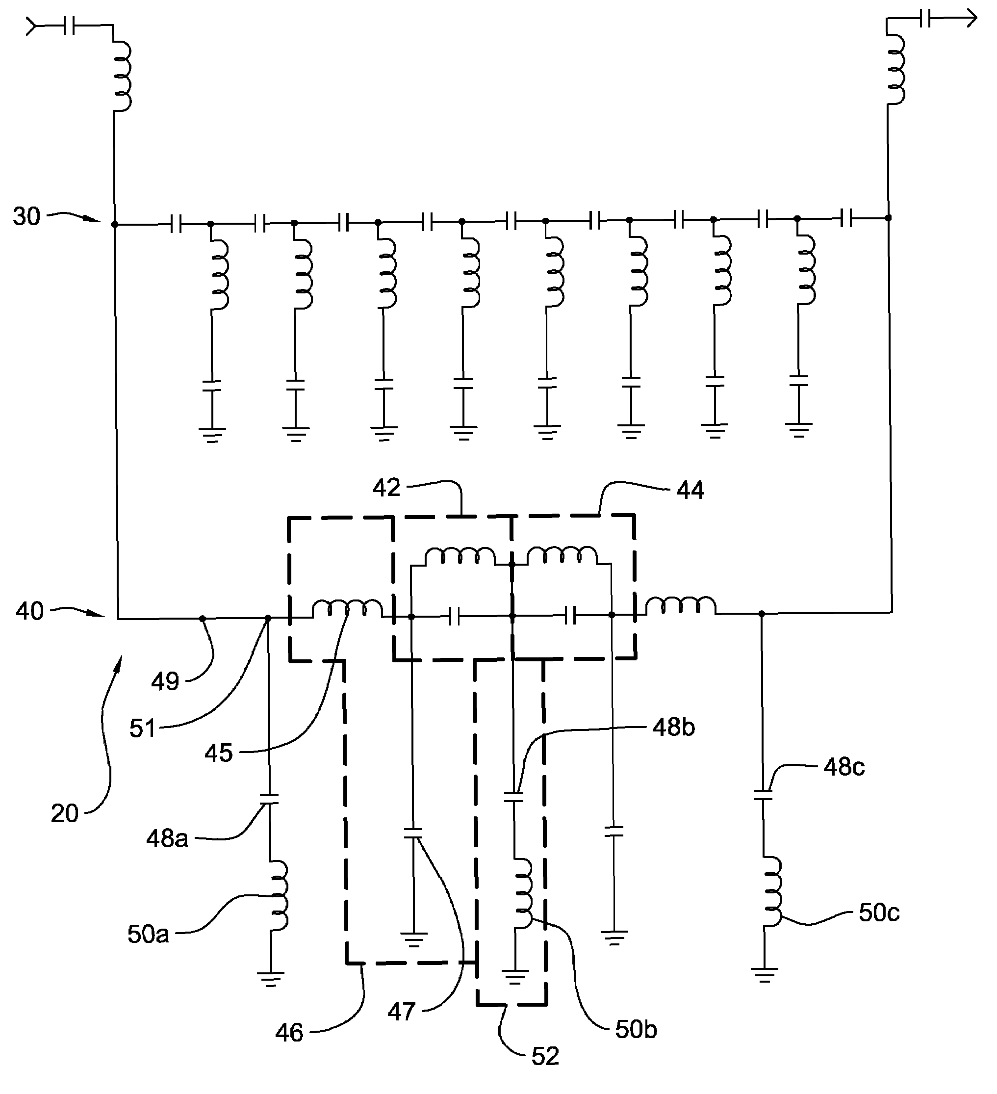
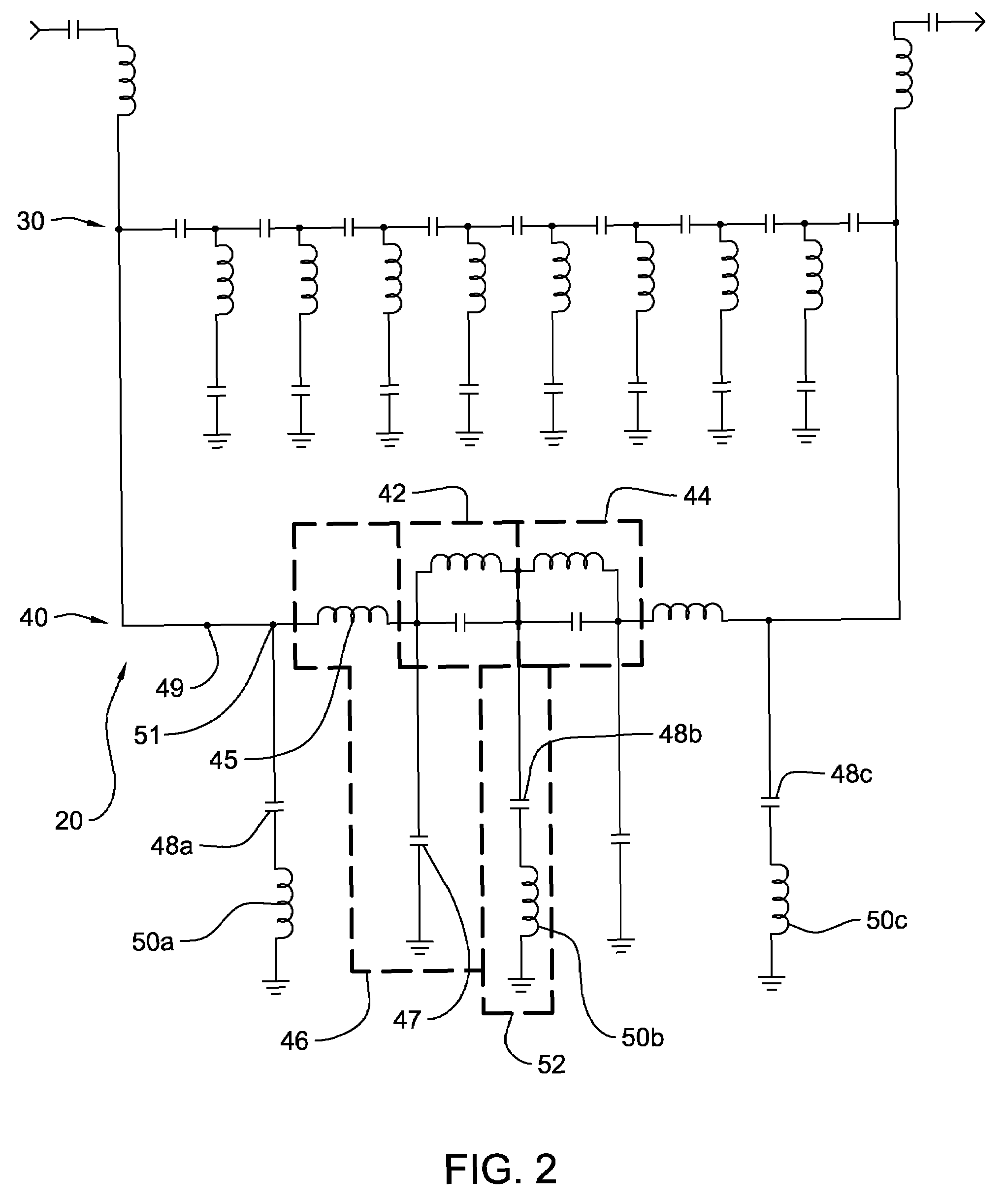
[0019]As known in the art, the lowpass leg of a diplex bandstop filter is one of four types: (1) minimum capacitor filter, (2) minimum inductor filter, (3) minimum inductor elliptic function filter, and (4) minimum capacitor elliptic function filter. In the present invention, a hybrid filter is defined as a filter which is a hybrid of at least two...


PUM


Abstract

A hybrid diplex bandstop filter includes a lowpass filter circuit which passes a first range of frequencies and a highpass filter circuit passes a third range of frequencies. The filter blocks a second range of frequencies. The third range of frequencies is higher than the second range and the first range. A tuning circuit tunes at least one re-resonance of a frequency inside the first range of frequencies to either within the second range of frequencies or outside an industry specified upper limit which is in the third range of frequencies.

Description

FIELD OF THE INVENTION[0001]This invention relates generally to the field of diplex filters used in cable television systems, and more particularly to a low pass diplex filter which reduces high pass resonance.BACKGROUND OF THE INVENTION[0002]A diplex circuit, or more simply a “diplexer,” is a device which separates or combines RF signals. Diplexers are used in connection with CATV equipment in a number of situations, some of which use two diplexers back-to-back. These include step attenuators, power bypass circuits, cable simulators and equalizer circuits. Many of the prior art CATV diplex circuits are used to act on signals traveling in so-called forward and return paths, e.g., relatively high frequency RF signals pass from a source of such signals to a television set at subscriber premises in the forward direction over one leg of the circuit while lower frequency (DC) signals pass from the premises in the return direction.[0003]Bandstop or “notch” filters are commonly employed in...

Claims


Application Information

Patent Timeline
Patent Type & Authority Patents(United States)
IPC IPC(8): H03H7/01
CPCH03H7/0115H03H7/175H03H7/1758H03H7/1766H03H7/1783H03H7/1791H03H2007/013H03H2250/00
Inventor SHAFER, STEVEN
Owner PPC BROADBAND INC
Why Eureka
Try Eureka