Systems and methods for TDOA/FDOA location

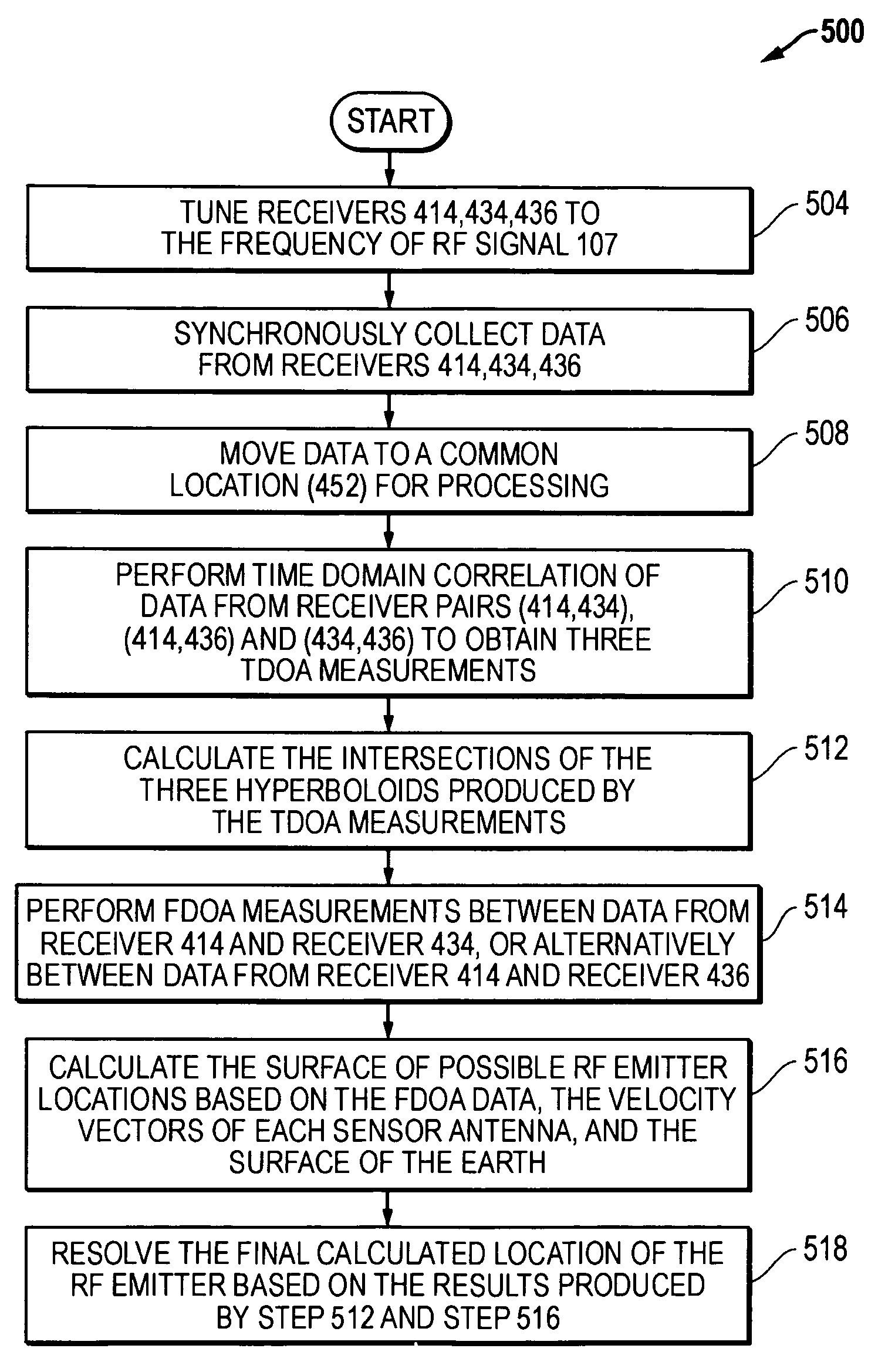
a technology of tdoa/fdoa and location method, which is applied in the direction of direction finders, instruments, measurement devices, etc., can solve the problems of increasing operation costs and complexity, not being able to reposition the two aircraft for subsequent tdoa/fdoa measurements, and requiring additional costs and complexity associated with the line of bearing equipment, so as to reduce operational complexity and cost

Inactive Publication Date: 2009-03-24
L 3 COMM INTEGRATED SYST +1
View PDF19 Cites 30 Cited by
  • Summary
  • Abstract
  • Description
  • Claims
  • Application Information

AI Technical Summary

Benefits of technology

[0010]The disclosed systems and methods may therefore be advantageously implemented to locate electromagnetic signal emitters of unknown location without the operational costs associated with a third sensing platform, without the expensive equipment costs of a system that can produce a line of bearing, and without requiring time to reposition the sensing platforms. This translates to lower costs and reduced operational complexity as compared to conventional TDOA / FDOA emitter location methods. Furthermore, the disclosed systems and methods may be implemented using sensor circuitry, sensor, and sensing platform equipment specifically designed and manufactured for emitter geo-location operations using co-located sensors, or may be implemented using existing geo-location system equipment, e.g., by retrofitting a sensing platform of an existing system (e.g., Guardrail Common Sensor system) with co-located sensors.

Problems solved by technology

However, only one of these possible geo-locations is real, the other possible geo-locations in the set are purely mathematical solutions that are not the real location of the radio emitter.
However, the necessity for utilizing a third aircraft increases operation costs and complexity.
However, where the RF signal emitter is only transmitting intermittently or only active for a short period of time, there may not be sufficient time to reposition the two aircraft for making subsequent TDOA / FDOA measurements.
While such a technique allows the location of a RF signal emitter to be determined by measuring a set of TDOA / FDOA data at a single position of the two aircraft, it requires additional costs and complexity associated with the line of bearing equipment.

Method used


Image

  • Systems and methods for TDOA/FDOA location
  • Systems and methods for TDOA/FDOA location
  • Systems and methods for TDOA/FDOA location

Examples


Embodiment Construction

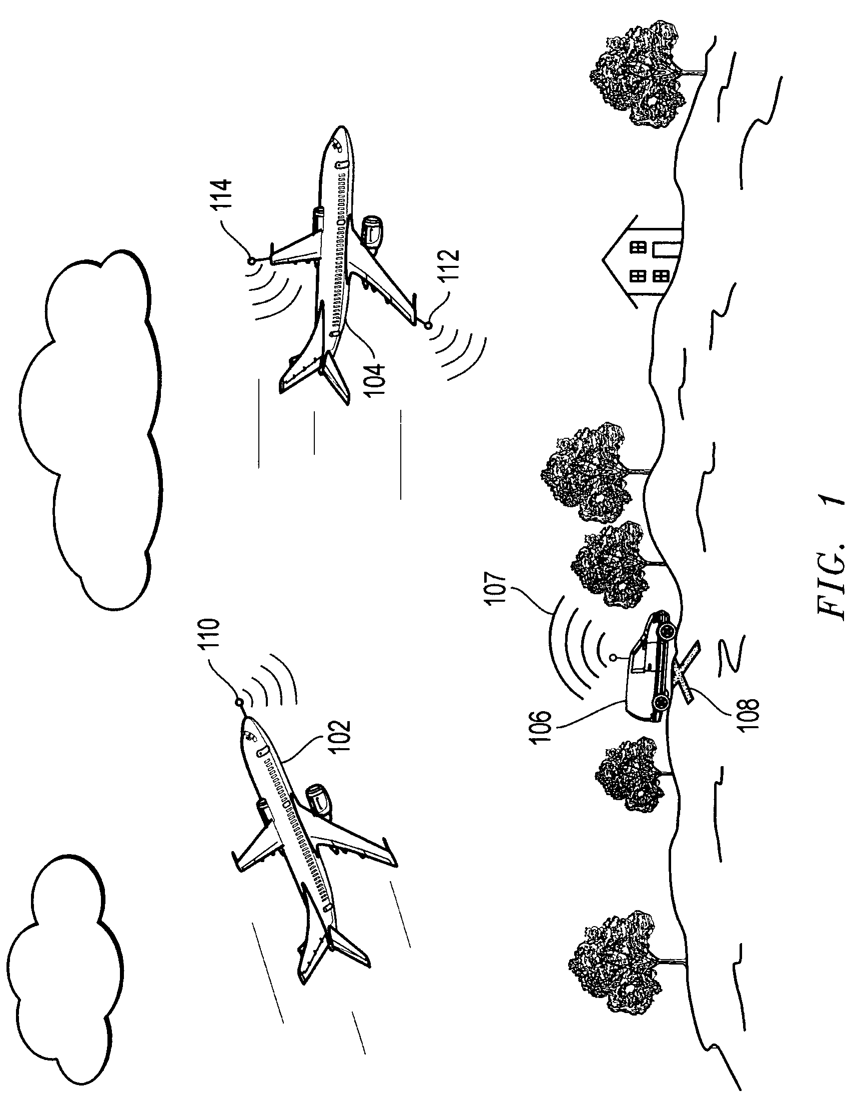
[0021]FIG. 1 is a simplified illustration of one embodiment of the disclosed systems and methods as it may be implemented to determine the geo-location of an electromagnetic radiation emitter in the form of an earth-based RF emitter 106. In the illustrated embodiment, RF emitter 106 is shown transmitting a RF signal 107 in a relatively short burst (e.g., RF transmission time of less than or equal to about two seconds) from a given geo-location 108 marked by a “X” in FIG. 1. In the illustrated embodiment, earth-based RF emitter 106 is shown as a single mobile emitter that may be stationary or moving at the time of transmission of the RF signal. However, it is also possible RF emitter may be a stationary (e.g., permanently positioned) emitter, and / or that multiple RF emitters may be present.

[0022]The disclosed systems and methods may be employed to locate any type of mobile or stationary device that is suitable for emitting electromagnetic radiation having a signal strength that is de...


PUM


Abstract

Systems and methods that may be implemented to determine the location of an emitter of electromagnetic radiation, such as an RF signal emitter having an unknown location, using at least two electromagnetic radiation sensor antennas that are co-located on a single sensing platform in combination with at least one other electromagnetic radiation sensor antenna located on another sensing platform.

Description

BACKGROUND OF THE INVENTION[0001]1. Field of the Invention[0002]This invention relates generally to location of emitters of electromagnetic radiation, and in one example, to Time Difference of Arrival (“TDOA”) / Frequency Difference of Arrival (“FDOA”) location of emitters of electromagnetic radiation.[0003]2. Description of the Related Art[0004]TDOA / FDOA techniques have been employed in the past to determine the location of emitters of electromagnetic radiation, such as radio frequency (“RF”) emissions. Using such techniques, the time difference (TDOA) in reception of a radio signal received at the sensing platforms of two spaced apart aircraft may be used to define a hyperboloid upon which the RF emitter of interest is located. Frequency difference (FDOA) in reception of the same radio signal at the sensing platforms of the two spaced apart aircraft may be generated by flying the spaced apart aircraft at different velocities and headings relative to the RF emitter, and may be used t...

Claims


Application Information

Patent Timeline
Patent Type & Authority Patents(United States)
IPC IPC(8): G01S1/24
CPCG01S5/06G01S5/12
Inventor STROUD, KEN A.
Owner L 3 COMM INTEGRATED SYST
Why Eureka
Try Eureka