
Packet routing

a packet and packet technology, applied in the field of packet routing, can solve the problems of under-utilization of network resources using shortest path first, scatter routing performance in simulations, and performance only slightly less well, so as to reduce the memory needs of routers and reduce complexity. the effect of overhead

Inactive Publication Date: 2009-03-24
BRITISH TELECOMM PLC
View PDF30 Cites 1 Cited by
  • Summary
  • Abstract
  • Description
  • Claims
  • Application Information

AI Technical Summary

Benefits of technology

[0014]Further advantages of the present invention are that scatter routing does not require global knowledge. Needing only local knowledge makes scatter routing dynamically adaptive and reduces the memory needs of the routers, compared with routing protocols that maintain knowledge of multiple end-to-end paths. Scatter routing can also make use of existing SPF routing infrastructure and methodology. The advantage of this is that its implementation would not require radical change to what is already in place. Scatter routing would add an overhead of complexity to the existing routing system. However, compared with some complex schemes that have been proposed, using RSVP and MPLS, our proposal is relatively simple.

Problems solved by technology

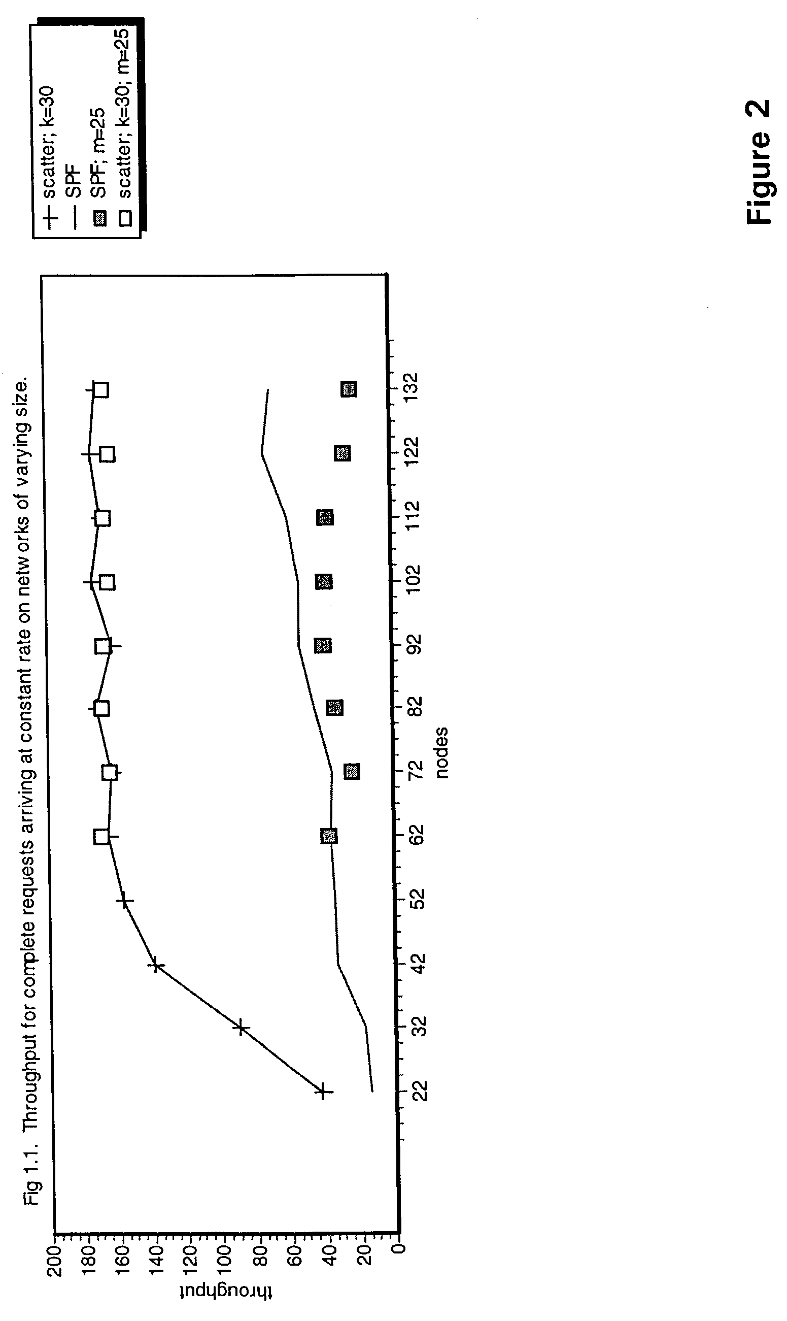
Advantageously scatter routing gives significantly better throughput than SPF in congested conditions, for a wide range of network connectivities, and performs only slightly less well when the network has no congestion.
Whilst there are network topologies that can be devised (Optimising Network Architectures, P Bladon, G Chopping, B Jensen and T Maddern, IEE 16th UK Teletraffic Symposium on ‘Management of quality of Service—The New Challenge’).that are inherently good at balancing traffic load, asymmetric demand for services will still result in under-utilisation of network resources using Shortest Path First.
Connectivity with m greater than 25 does not improve the performance of scatter routing in our simulation.

Method used


Image

  • Packet routing
  • Packet routing
  • Packet routing

Examples


Embodiment Construction

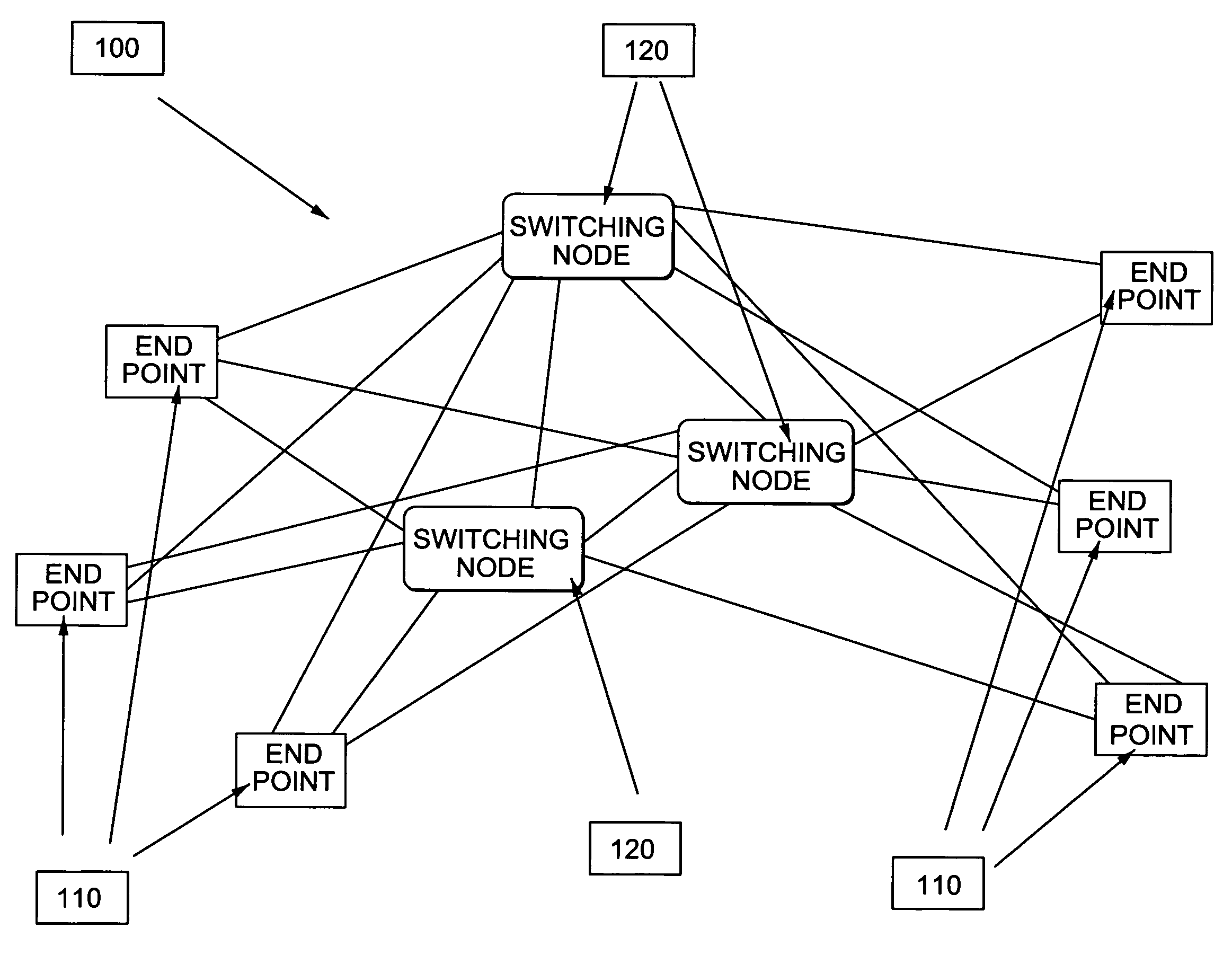
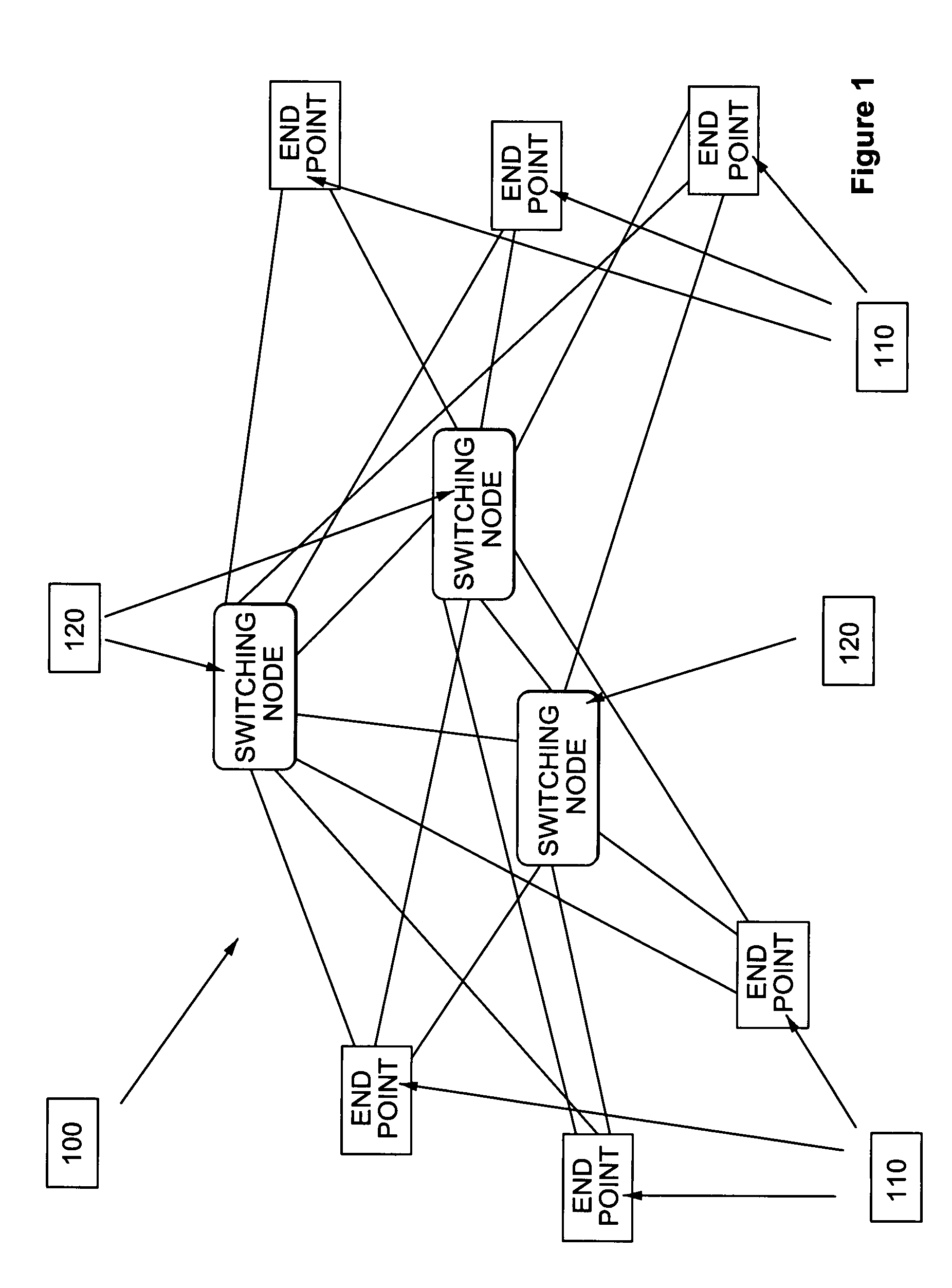
[0019]FIG. 1 shows an example of the sort of network that can be used with the method of the present invention. Network 100 comprise a plurality of switching nodes 120 and a plurality of endpoint nodes 110. In the network shown in FIG. 1 there are six endpoint nodes 110 and three switching nodes 120, all of which are fully inter-connected (i.e. there is a direct connection for each node to all of the other nodes, whether an endpoint node 110 or a switching node 120, in the network. As networks grow it becomes infeasible to have a fully interconnected network and each a maximum number of connections, m, is defined for each network node. The value of m may be constant for all of the nodes within the network or constrained within a range of values.

[0020]In order to demonstrate the advantages of the present invention a number of different networks were generated in order to perform a number of simulations. The rules used to construct the simulated network were in general as follows. Fir...


PUM


Abstract

A routing protocol scatters a stream of packets along a number of parallel paths, the packets being treated independently. The next hop for each packet is chosen probabilistically by comparing the ‘resistance’ of available options. The resistance of a given hop depends upon the time the packet would spend in an output buffer from the current node, the time the packet would spend in the input buffer of the next hop node, the transfer time between the nodes and the number of hops that the packet would take from the current node to the ultimate destination of the packet using the shortest path. This routing protocol is more efficient that shortest path first routing under simulation.

Description

[0001]This application is the US national phase of international application PCT / GB01 / 03012 filed 5 Jul. 2001 which designated the U.S.BACKGROUND[0002]1. Technical Field[0003]This invention concerns the routing of packets in packet-based networks.[0004]2. Related Art[0005]The performance of the internet is renowned for its inconsistency. Sometimes a document can be downloaded instantly; at other times, the same document takes a hundred times longer to appear. As a result, there is a lot of research effort directed at reducing internet congestion. Some groups favour resource rationing (K Danielsen and M Weiss, “User Control Modes and IP Allocation”, MIT Workshop on Internet Economics, March 1995), other groups seek to increase routing intelligence (G Di Caro and M Dorigo, “AntNet: Distributed Stigmergetic Control for Communication Networks”, J. Artificial Intelligence Research, 9, p. 317, 1998) to avoid congested regions of the network. It is generally understood that Shortest Path F...

Claims


Application Information

Patent Timeline
Patent Type & Authority Patents(United States)
IPC IPC(8): H04L12/26G01R31/08G06F11/00G08C15/00H04J3/14H04L45/24
CPCH04L45/00H04L45/24
Inventor TATESON, JANE EMARSHALL, IAN W
Owner BRITISH TELECOMM PLC
Learn More