Frame signal waveform observation apparatus and method

a frame signal and waveform technology, applied in the field of trigger signal generating system and frame signal waveform observation system, can solve problems such as the inability to transmit data signals correctly, and achieve the effect of suppressing the phase variation of random noise type of frame signals

Inactive Publication Date: 2009-03-24
ANRITSU CORP
View PDF7 Cites 8 Cited by
  • Summary
  • Abstract
  • Description
  • Claims
  • Application Information

AI Technical Summary

Benefits of technology

[0069]displaying, as related to each other, averaged waveform information of the clock and the averaged waveform information in the neighborhood of the designated arbitrary bit position of the frame signal in order to make it possible to measure a phase variation dependent on a bit pattern of the frame signal by comparison with the averaged waveform information of the clock while suppressing the phase variation of random noise type of the frame signal.

Problems solved by technology

In a digital synchronous network for transmitting a data signal multiplexed as a frame signal such as a digital synchronous transmission system including a synchronous digital hierarchy (SDH), synchronous optical network (SONET) or optical transport network (OTN), a large phase fluctuation (jitter or wander), if any, of the data signal would make it impossible to transmit the data signal correctly.

Method used


Image

  • Frame signal waveform observation apparatus and method
  • Frame signal waveform observation apparatus and method
  • Frame signal waveform observation apparatus and method

Examples


Embodiment Construction

[0077]An embodiment of the invention is explained below with reference to the drawings.

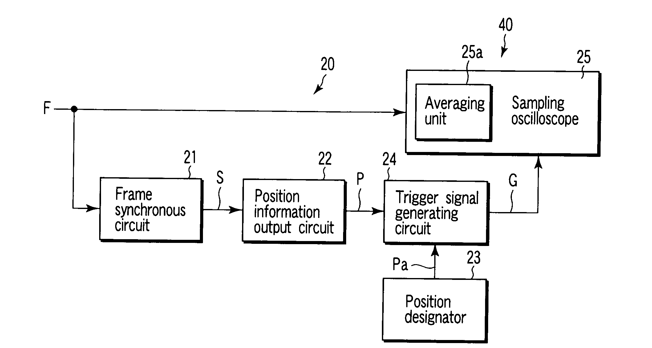
[0078]FIG. 1 is a block diagram for explaining the configuration according to an embodiment of the invention applicable to a trigger signal generating system including a trigger signal generating apparatus 20 and method and a frame signal waveform observation system including a frame signal waveform observation apparatus 40 and method using the trigger signal generating system.

[0079]Specifically, the trigger signal generating apparatus 20 includes a frame synchronous circuit 21 which receives a frame signal of a predetermined bit rate and outputs a synchronous signal in synchronism with an input timing of leading data of the frame signal, a position information output circuit 22 which receives the synchronous signal output from the frame synchronous circuit 21 and outputs the position information indicating an input bit position of the frame signal, a position designator 23 which designates an arb...


PUM


Abstract

A trigger signal generating apparatus includes a frame synchronous circuit which receives a frame signal having a predetermined bit rate and outputs a synchronous signal in synchronism with an input timing of leading data of the frame signal, a position information output circuit which receives the synchronous signal output by the frame synchronous circuit and outputs the position information indicating an input bit position of the frame signal, a position designator which designates an arbitrary bit position of the frame signal, and a trigger signal generating circuit which outputs a trigger signal at a timing when the position information output by the position information output circuit is coincident with the arbitrary bit position designated by the position designator. A trigger is generated accurately at an arbitrary bit position of the frame position.

Description

[0001]This application is a U.S. National Phase Application under 35 USC 371 of International Application PCT / JP2004 / 009988 filed Jul. 7, 2004.TECHNICAL FIELD[0002]The present invention relates to a trigger signal generating system and a frame signal waveform observation system using the trigger signal generating system, or in particular to a trigger signal generating system including a trigger signal generating apparatus and method and a frame signal waveform observation system including a frame signal waveform observation apparatus and method using the trigger signal generating system which employ a technique capable of accurate triggering at an arbitrary bit position of the frame signal in order to accurately acquire and observe the waveform at an arbitrary bit position.BACKGROUND ART[0003]In a digital synchronous network for transmitting a data signal multiplexed as a frame signal such as a digital synchronous transmission system including a synchronous digital hierarchy (SDH), ...

Claims


Application Information

Patent Timeline
Patent Type & Authority Patents(United States)
IPC IPC(8): H04J3/06H04J3/02G01R13/20G01R13/32G01R13/34
CPCG01R13/32G01R13/345
Inventor AMAGAI, MITSUO
Owner ANRITSU CORP
Why Eureka
Try Eureka