Speaker edge and resonator panel assembly

a resonator panel and speaker edge technology, applied in the direction of transducer diaphragms, electrical apparatus casings/cabinets/drawers, instruments, etc., can solve the problem of non-uniform vibration damping profiles, achieve damping acoustic vibrations, increase damping capacity, and influence the quality of sound emitted

Inactive Publication Date: 2009-03-31
MUTO KEIKO +1
View PDF33 Cites 15 Cited by
  • Summary
  • Abstract
  • Description
  • Claims
  • Application Information

AI Technical Summary

Benefits of technology

[0019]Manufacturing considerations often dictate that the acoustic damping profile of a speaker edge be changed abruptly from one vibration damping level to another. Embodiments provides the flexibility to accommodate such abrupt changes in the acoustic vibration damping profile of a speaker edge without unacceptably degrading the performance of the speaker. The characteristics of the acoustic output from a speaker assembly often depends somewhat on the shape and location of the juncture between the acoustically different sections. Certain embodiments are suitable for use in flat highly elongated speakers such as are typically placed on the edges of planar computer and television displays or the like wherein the aspect ratio of the planar elongated resonator is as much as approximately 2 to 1 or more. Embodiments of elongated resonator panels include, for example, generally flat panels, and generally arcuate panels with simple or compound curves.
[0020]The angle of the ribs that extend between the opposed panels in the elongated resonator panel may be varied from approximately 5 to 35 degrees from the longitudinal axis of the elongated resonator panel. In general, in optimizing an embodiment by varying the angle of the ribs, all other variables being held constant, the quality of higher frequency sounds improves as the angle increases, and the quality of the lower frequency sounds improves as the angle of the ribs decreases. Quality is determined by a trained human ear, because instruments are generally not capable of making the fine distinctions that are required in the final optimization of the speaker assembly.
[0027]One convenient way of varying the physical properties, and thus the acoustic vibration damping characteristics, along the circumference of the speaker edge is to use more pre-formed foamed polymeric material in one area and thermally compress it more in one section to get a speaker edge with a uniform physical form but with longitudinally varying physical properties. The material is generally denser, stiffer, and exhibits more acoustic vibration damping influence or capacity where there is more material compressed into the same volume.
[0030]The non-uniform vibration damping characteristics of the speaker edge substantially influence the quality of the sound emitted by the speaker. For a round resonator plate with the vibration emitter located in the center of the plate, the vibration damping characteristics of the speaker edge should generally be substantially uniform. If the vibration emitter is shifted away from the center, the speaker edge should be configured so that the section of the speaker edge that is radially furthest from the vibration emitter damps vibrations more strongly than does the section closest to the vibration emitter. Where, for example, a square resonator panel is employed the speaker edge at the corners should generally damp the acoustic vibrations more strongly than at the mid-points of the sides. As the aspect ratio of the resonator panel increases the acoustic vibration damping profile of the speaker edge should show an increased damping capacity in the sections that are furthest from the vibration emitter.
[0031]While acoustic parameters such as volume and frequency can be accurately measured with suitable instruments, the final arbiter of the quality of the sound from a speaker is a trained human ear. Final adjustments to the vibration damping characteristics of the various sections of a speaker edge will usually be made by trial and error. The measuring instrument used in making such final trial and error adjustments will be the trained human ear. The predetermined non-uniform acoustic vibrational damping provided according to the present invention is tolerant enough of small manufacturing variations that speaker systems employing it can be mass produced at a reasonable cost while maintaining substantially the same acoustic characteristics.

Problems solved by technology

In particular, embodiments provide a speaker edge with a non-uniform vibration damping profile or characteristics around its periphery (a complex speaker edge), and a ribbed elongated resonator panel in which the ribs are not aligned with the longitudinal or lateral axis of the elongated resonator panel.

Method used


Image

  • Speaker edge and resonator panel assembly
  • Speaker edge and resonator panel assembly
  • Speaker edge and resonator panel assembly

Examples


embodiment 134

[0070]FIGS. 11 through 15 and 17 illustrate in plan form various embodiments of complex speaker edges according to the present invention. In these embodiments the resonator panel 147, the radiator 144 and the driver 146 are common to all embodiments. In all embodiments the speaker edge is mounted to the outer periphery of the resonator panel 147. In the embodiment 134 of FIG. 11 the complex speaker edge 150 has a first section 148 and a second section 154. Different speaker vibration damping capacities are provided by inserting a body of material in the longitudinally extending channel as shown, for example, in cross-section in FIGS. 7 through 10.

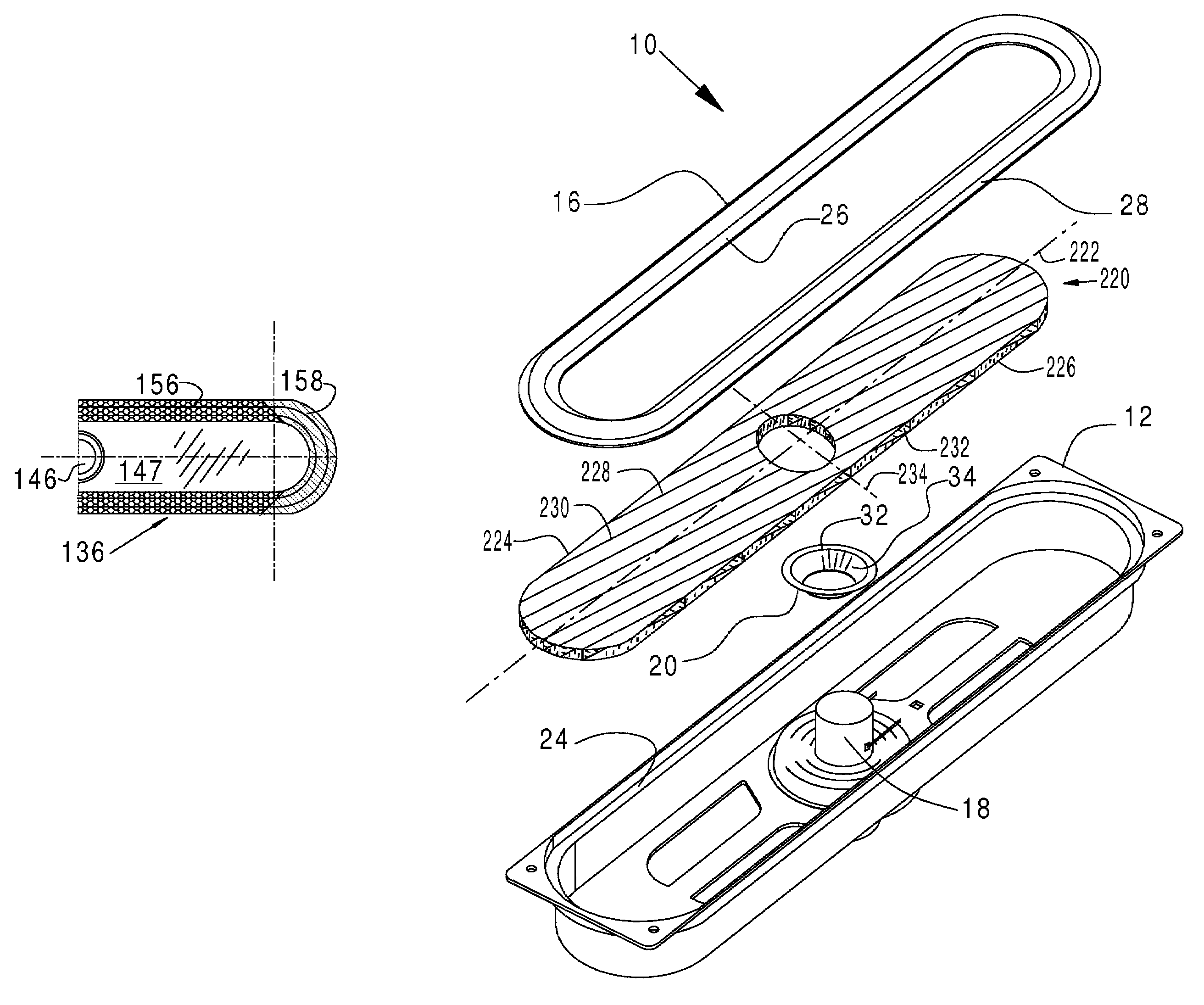
[0071]In the embodiment 136 of FIG. 12 the complex speaker edge has a first section 156 and a second section 158. Different speaker edge vibration damping capacities are provided by using a greater volume of material in second section 158 as shown, for example, in cross-section in FIGS. 5 and 6. The embodiment 138 of FIG. 13 is similar to t...

embodiment 140

[0072]In the embodiment 140 of FIG. 14, the opposed boundaries 168 and 166 of the complex speaker edge have about the same characteristics. The channel 164 has physical characteristics that differ from those of the opposed boundaries 166 and 168. The channel in end section 170 differs in its physical characteristics from channel 164 in the median section.

embodiment 142

[0073]The embodiment 142 in FIG. 15 is similar to the embodiment of FIG. 14 except that the end of the resonator panel 174 is squared off rather than being rounded, and the speaker edge is shaped to conform to the plan form of the resonator panel 174. The inner 182 and outer 176 boundaries are similar in their physical characteristics. The physical characteristics of the channel 178 in the first section are different from those in the channel 180 in the second section.

[0074]FIG. 17 is provided to illustrate a single speaker edge in which the acoustic vibration damping properties of the speaker edge 188 are substantially constant around the entire longitudinal length of the speaker edge.

[0075]The various speaker edges illustrated in FIGS. 11 through 15 can be oriented with the pleat or channel depending in either direction from the normally outer surface of the resonator panel, and there may be two or more channels in a single speaker edge, if desired. The pleat or longitudinally ext...


PUM


Abstract

A complex speaker edge and asymmetric resonator panel in which the acoustic vibration damping capacity of the speaker edge varies longitudinally around the speaker edge. The resonator panel has an aspect ratio of approximately 1.3:1 or more, and is composed of top and bottom panels held in spaced apart relationship by a plurality of longitudinally extending ribs extending therebetween. The ribs extend at an angle of from approximately 5 to 35 degrees to the longitudinal axis of the panel. The angle is acoustically matched to the complex speaker edge to improve the accuracy with which said acoustic vibration is reproduced. The effectiveness of the differential damping capacity of the edge in improving the quality of sound output from a speaker assembly is determined by observing the average magnitude of the excursions of the sound level pressure versus frequency curves for comparable complex and single speaker edges, particularly in the 200 to 10,000 Hertz range. The speaker edge and the angle of the ribs are acoustically matched by iteratively adjusting the edge and / or the angle in response to the quality of the sound that is perceived by a trained human ear.

Description

RELATED APPLICATIONS[0001]This is a continuation-in-part of Ser. No. 10 / 794,479, filed Mar. 5, 2004 now abandoned.BACKGROUND OF THE INVENTION[0002]1. Field of the Invention[0003]The invention relates in general to the interrelationship between complex speaker edges and especially configured resonator panels wherein speakers with high aspect ratio ribbed resonator plates are mounted to supporting frames through complex speaker edges. Embodiments include complex speaker edges with non-uniform vibration damping profiles or characteristics around their peripheries, and resonator plates with non-axially aligned ribs. In this field, the quality of the emitted sound is optimized, for example, by matching the vibration damping profile and the angle at which the ribs extend.[0004]2. Description of the Prior Art[0005]Speaker edges composed of various flexible materials had been widely employed in the mounting of acoustic vibration plates, particularly conical shaped vibration plates, to suppo...

Claims


Application Information

Patent Timeline
Patent Type & Authority Patents(United States)
IPC IPC(8): G10K13/00H04R1/22H04R7/06H04R7/20H04R7/04H04R7/16H04R1/00H04R7/00H04R9/06H04R11/02
CPCH04R7/20
Inventor MUTO, KEIKOYANAGAWA, MAYUKI
Owner MUTO KEIKO
Why Eureka
Try Eureka