Sensing switch and detecting method using the same

a technology which is applied in the field of sensing switch and detecting method using the same, can solve the problems of inability to digitally output, large system, and difficult miniaturization of equipment required, and achieve the effect of effectively removing background signals and being easily identified

Inactive Publication Date: 2009-03-31
SAMSUNG ELECTRONICS CO LTD
View PDF5 Cites 1 Cited by
  • Summary
  • Abstract
  • Description
  • Claims
  • Application Information

AI Technical Summary

Benefits of technology

[0018]The sensing plate may be composed of a material such that the sensing plate can be easily bent by the respective repulsive and attractive forces of the push-out electrode and the pull-in electrode. Therefore, the entire sensing plate or at least a portion of the sensing plate contacting the switching electrode may be composed of an electrical conducting material so that the switching electrodes on the substrate can be connected to each other when the sensing plate is bent downward.
[0019]The connecting beam may be narrower and thinner than the sensing plate, and thus can be easily bent by the respective repulsive and attractive forces of the push-out electrode and the pull-in electrode. The connecting beam may be integrated with or separated from the sensing plate.
[0024]The receptor may be immobilized on one of two receptor binding regions. Preferably, different ligands are respectively immobilized on the two receptor binding regions. In this case, one of two ligands may act as a reference receptor and thus differential detection can be performed and a background signal can be effectively removed.
[0027]The sensing circuit may performs sensing and analyzing at the same time in response to output signals from the ‘and / or’ logic circuits. The sensing circuit may have at least one input line and at least one output line. The sensing and analyzing of a plurality of receptors can be performed at the same time by applying a current to the input line and measuring the current from each output line. In addition, the signal processing is not required after the signal sensing. That is, the binding of the different receptors in sensing switches forming a circuit can be effectively analyzed by only confirming whether a current is output from the output line, for example, whether a lamp is on or off, without processing the sensed signal.
[0030]A receptor may be immobilized on only one of two receptor binding regions of the sensing switch. Preferably, different ligands may be respectively immobilized on two receptor binding regions such that differential binding of the different ligands can be sensed. In this case, the two receptor binding regions move like a seesaw such that an end of a sensing plate to which more receptors are bound descends. At this time, one of two kinds of ligands acts as a reference receptor, and thus a background signal can be effectively removed.
[0031]In a conventional electrical sensing method, resistance, impedance, the amount of a current, and the like are measured using a measuring apparatus and then signal processing is performed. On the other hand, according to the present invention, the binding of a receptor can be easily identified by confirming whether a current flows through a sensing switch or not, for example, by confirming whether a lamp is on or off.

Problems solved by technology

However, it is difficult to miniaturize the equipment required for such an optical sensing method and the result cannot be digitally output.
However, the electrochemical methods also require a labeling process.
Therefore, the entire system is bulky, many expensive apparatuses are required, and skilled engineers are required to perform each operation.
Even when all these requirements are complied with, it takes a long time to obtain a final result and a noise is guaranteed in connections between apparatuses.

Method used


Image

  • Sensing switch and detecting method using the same
  • Sensing switch and detecting method using the same
  • Sensing switch and detecting method using the same

Examples


example 1

[0094]Torque was measured using the sensing switch illustrated in FIGS. 9A and 9B under the following condition: 80% non-specific binding to mismatched receptor (single mismatch receptor, hypothetically); immobilized 25 mer receptor DNA density of 2×10¹² molecules / cm2; 100% hybridization with perfect matched DNA (25 mer); a receptor of 5′ SH-C6-AGATCAGTGCGTCTGTACTAGCACA 3′ (See A. Peterson, the effect of surface receptor density on DNA hybridization, Nucleic Acid Research 2001, 29, 24, pp 5163-5168).

[0095]The results of steady state analysis are described below.

[0096]Total effective charge (q)=reactive surface area x molecules / area×number of electrons / molecule×charge / electron=6×10⁻¹¹ C;

[0097]the electric field=10V / (50×10 um)=2×10⁵ N / C; and

[0098]Fe=1.2×10⁻⁹ N.

[0099]Accordingly, as described below, the sensor did not operate because the electrostatic torque, was smaller than the mechanical restoring torque.

[0100]Electrostatic Torque=Fe×40 μm=4.8×10⁻¹⁰ Nm

[0101]Restoring torque=9.22×10−...

example 2

[0109]In order to confirm whether the sensing switch shown in FIG. 10 can act as a switch, a simulation experiment was conducted in which a nucleic acid used as biomolecule was sensed using the apparatus illustrated in FIG. 9. (See A. Peterson, the effect of surface receptor density on DNA hybridization, Nucleic Acid Research 2001, 29, 24, pp 5163-5168). ANSYS 8.0 (obtained from ANSYS, Inc., USA) was used as a simulation program, a shell 93 (suited for large deflection) was used as an element, a beam was made of gold, young's modulus was 75 GPa (silicon˜169 GPa), poisson's ratio was 0.42, a density was 1.932×10⁴ kg / m3 (silicon˜2.33 e3 kg / m3), the beam had a thickness of 1 μm, the relative permitivity of a buffer solution was 80, a gap between two electrodes was 100 μm, an applied potential was 10 V, an immobilized 25 mer receptor DNA density was 2×10¹² molecules / cm2, 100% hybridization with perfectly matched DNA (25 mer) was performed, and a receptor used was 5′ SH-C6-AGATCAGTGCGTCT...

example 3

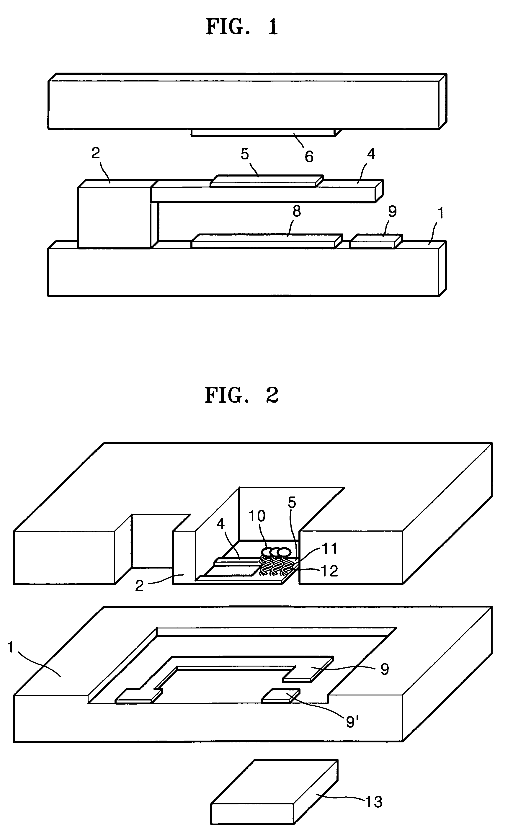
[0111]A force generated between the magnetic bead and the magnetic generation device that was sufficiently strong to move a switch but not greater than a binding force between the receptor and the ligand was measured using the sensing switch shown in FIG. 2

[0112]A BioMag® BM551 was used as the magnetic bead. Streptavidin as a ligand was bound to the surface of the magnetic bead. A neodium magnet was used as the magnetic field generation device. The magnetic bead and the neodium magnet had the following characteristics: Br=1.22 Tesla, μ0=1.26×10⁻⁶ H / m, magnetic mass susceptibility=2.54×10⁻³ m3 / kg, density=1.70×10³ kg / m3, magnetic susceptibility=4.31, bead diameter=1.50×10⁻⁶ m, V=1.77×10⁻¹⁸ m3, and L_magnet=0.003 m.

[0113]The magnetic force with respect to the distance between the magnetic bead and the magnetic filed generation device was measured using the values above and Formula 8.

[0114]Fmag=V⁢⁢χmμ0⁢(B→·∇)⁢B→=V⁢⁢χm2⁢μ0⁢∇(B→2)⁢⁢Bx=Br2⁡[L+xR2+(L+x)2-xR2+x2](8)

[0115]The results are sho...


PUM

PropertyMeasurementUnit
currentaaaaaaaaaa
relative dielectric constantaaaaaaaaaa

Abstract

Provided are a sensing switch and a sensing method using the same. The sensing switch includes: a substrate; a supporter on the substrate; a sensing plate that is connected to a side of the supporter and is in parallel with the substrate by a predetermined distance; a receptor binding region on an upper surface of an end portion of the sensing plate; an electric or magnetic field generation device that induces deflection of the sensing plate when a receptor bound to the receptor binding region is selectively bound to an electrically or magnetically active ligand; and a pair of switching electrodes that are separated by a predetermined distance and is connected when the sensing plate contacts the substrate due to the deflection of the sensing plate. A target material need not be labelled, a signal processing of a fluorescent or electrical detection signal using an analysis apparatus is not required, and a signal can be directly decoded by confirming whether a current flows through the switch.

Description

CROSS-REFERENCE TO RELATED PATENT APPLICATIONS[0001]This application claims the benefit of Korean Patent Application Nos. 10-2005-0010987 filed on Feb. 5, 2005, and 10-2005-0092668 filed on Oct. 1, 2005, in the Korean Intellectual Property Office, the disclosures of which are incorporated herein in their entirety by reference.BACKGROUND OF THE INVENTION[0002]1. Field of the Invention[0003]The present invention relates to an apparatus for sensing a biomolecule or a chemical material, and more particularly, to a sensing switch that physically moves due to an electrostatic force between an electrode having the same polarity as a ligand and another electrode having the opposite polarity to the ligand or due to a magnetic force between a magnetic bead bound to a ligand and a magnetic field generation device, thus acting as a switch, and a sensing method using the same.[0004]2. Description of the Related Art[0005]Effective sensing of biomolecules and chemical materials is required in a wi...

Claims


Application Information

Patent Timeline
Patent Type & Authority Patents(United States)
IPC IPC(8): C12M1/34
CPCG01N33/54373
Inventor YOO, KYU-TAEKIM, JOON-HOMIN, JUN-HONGJUNG, SUNG-OUKNAMGOONG, JI-NAKIM, KUI-HYUNSHIM, JEO-YOUNGNAMKOONG, KAK
Owner SAMSUNG ELECTRONICS CO LTD
Why Eureka
Try Eureka