Media integration layer

a technology of media integration and layer, applied in the field of computer systems, can solve the problems of visual and noticeable undesirable, and the limit of the traditional immediate mode model of accessing graphics on computer systems, and achieve the effect of not adversely affecting normal application performan

Inactive Publication Date: 2009-03-31
MICROSOFT TECH LICENSING LLC
View PDF91 Cites 66 Cited by
  • Summary
  • Abstract
  • Description
  • Claims
  • Application Information

AI Technical Summary

Benefits of technology

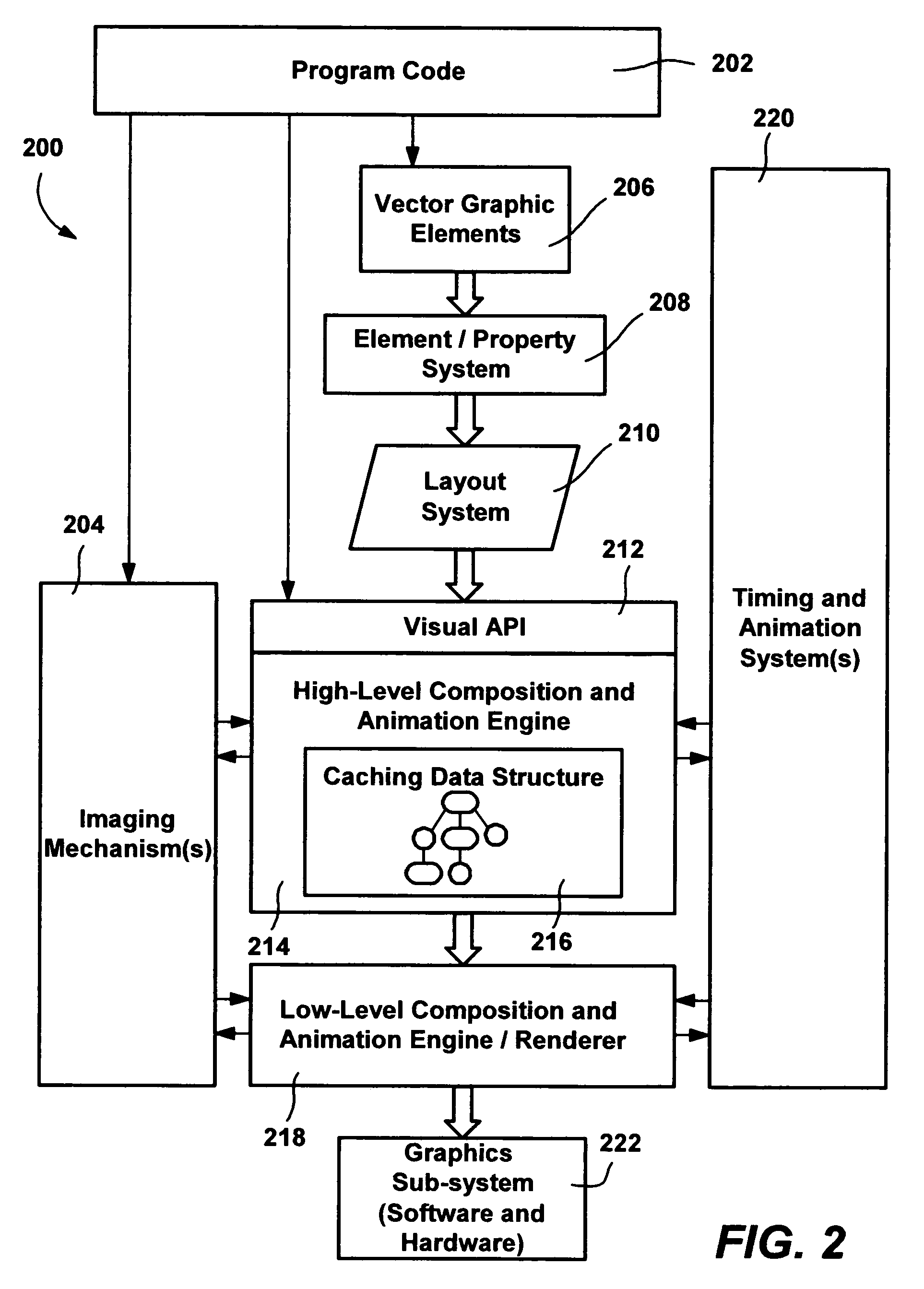
[0007]Briefly, the present invention provides a media integration layer which provides an API for programmers to accomplish possibly complex composition effects within their applications in a straightforward manner, while leveraging the graphics processing unit in a manner that does not adversely impact normal application performance. One aspect provides the ability to combine different media types (e.g., 2D, 3D, Video, Audio, text, imaging and so forth) and animate them together smoothly and seamlessly.
[0008]The MIL provides a graphics architecture for multi-stage composition, and a programming model that allows for functional parity at the programmatic and scripted interfaces. An API and script allows the creation of a retained structure or scene description that is composited when rendered, yet includes areas that have a more immediate-mode nature.
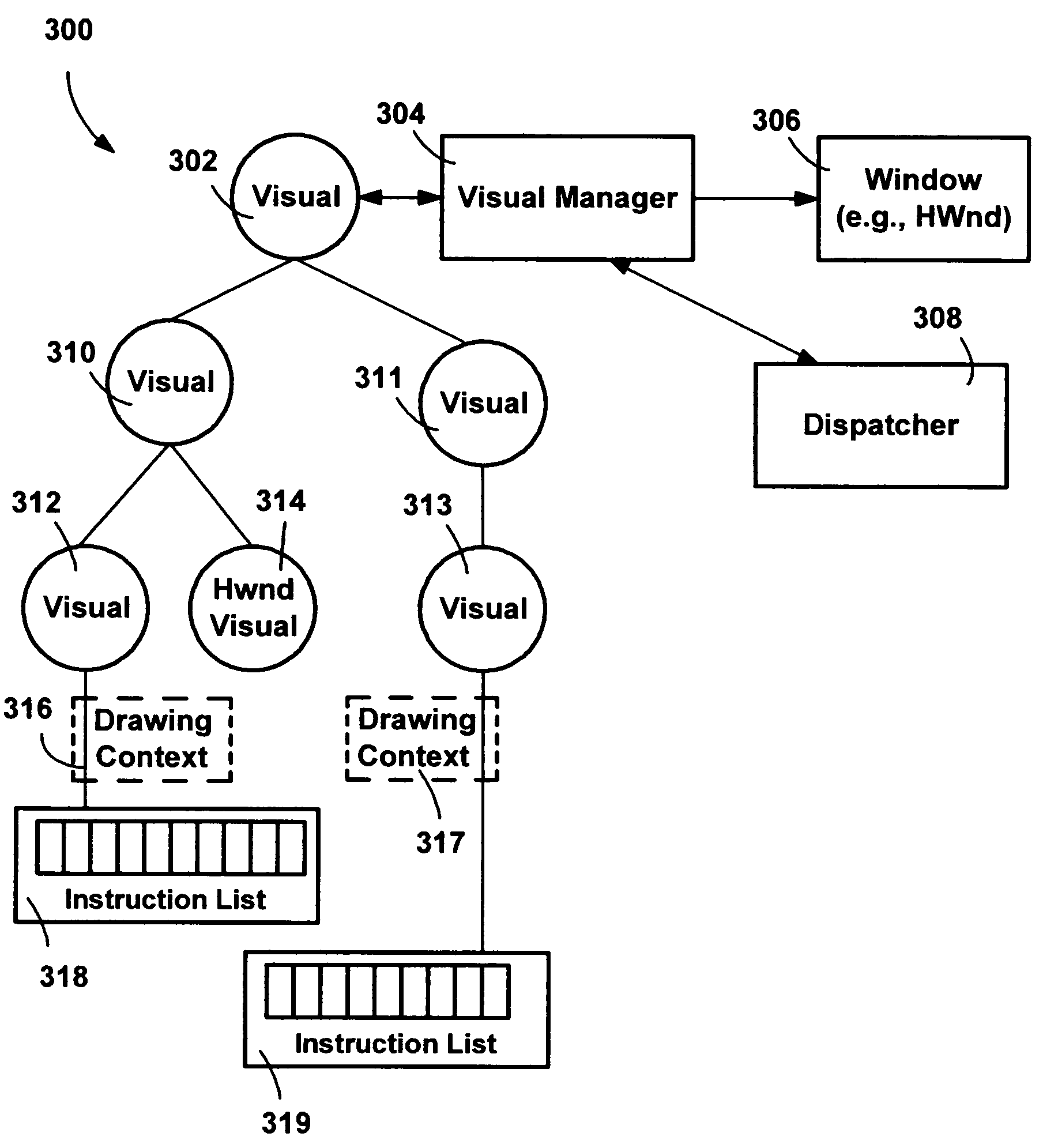
[0009]Via the interfaces, the MIL provides access to a data structure for storing visual information so that applications can take advantage of the graphics capabilities provided by the computer hardware. The interfaces support an element object model and a vector graphics markup language for using that element object model in a manner that allows program code developers to consistently interface with a scene graph data structure to produce graphics. The data structure may also be used for either directly rendering or for “compiling” the visual information so that it can be provided to a lower level graphics system for fast composition and animation.
[0017]A Geometry class of objects can be used for clipping, hit-testing, and rendering of 2D vector-based data with the Pen and Brush. The derived Geometry classes provide more specific building and enumeration semantics. A number of shape-specific Geometry types are provided, as well as a generalized PathGeometry that allows for explicit definition of more complex shaped Geometry. Geometry is an abstract base class. A GeometryCollection is a collection of multiple Geometry objects that have been combined using particular CombineMode operations on their defined area. This object allows easier building visual combinations of Geometry objects than is possible using strictly PathFigure objects within a PathGeometry.
[0021]Hit testing is used to pick visuals in a scene, and operates by starting from the top of the control tree, and returning a control or set of controls by a point or geometry. A control can define whether it is hit or not with support services including rendered geometry, bounding box, out-of-band geometry (hit region), image opacity or mask, and its own logic. The control can return specific hit-related data on hit. The hit test mechanism can filter hit test results in an efficient manner. The hit test walk is a deep right to left walk of the visual tree, with hits reported through a callback in z-order, top-to-bottom fashion. When descending, the hit tester views the filtering in terms of element level relationships, for example, a canvas with shapes, or a dock panel with an inner canvas. When a hit occurs, the hit tester can either continue processing further hits (if any), or stop.

Problems solved by technology

The limits of the traditional immediate mode model of accessing graphics on computer systems are being reached, in part because memory and bus speeds have not kept up with the advancements in main processors and / or graphics processors.
As a result, when complex graphics effects are attempted with conventional graphics models, instead of completing the changes that result in the perceived visual effects in time for the next frame, the changes may be added over different frames, causing results that are visually and noticeably undesirable.

Method used


Image

  • Media integration layer
  • Media integration layer
  • Media integration layer

Examples


examples

Valid an Invalid of Using Changeable Objects

[0327]The following section provides a summary of using and manipulating objects that derive from the Changeable class, by which objects, such as brushes, pens, and animations, are mutable as controlled by a programmer. Classes that derive from Changeable simulate mutability by automatically building an immutable version of themselves when used in a qualified use. As described above, a Changeable is considered used in a qualified use when the object is set into a Property System property, used as a sub-object in a complex Changeable object, or used in a DrawingContext command.

[0328]When developing applications with such objects, graphics and media system objects are generally created, set, used, and then never modified. For example, to set the background of a Button a programmer might use a SolidColorBrush, which derives from Changeable; but the programmer might never modify the button's background again over the course of the application....


PUM


Abstract

A media integration layer including an application programming interface (API) and an object model allows program code developers to interface in a consistent manner with a scene graph data structure in order to output graphics. Via the interfaces, program code adds child visuals to other visuals to build up a hierarchical scene graph, writes Instruction Lists such as geometry data, image data, animation data and other data for output, and may specify transform, clipping and opacity properties on visuals. The media integration layer and API enable programmers to accomplish composition effects within their applications in a straightforward manner, while leveraging the graphics processing unit in a manner that does not adversely impact normal application performance. A multiple-level system includes the ability to combine different media types (such as 2D, 3D, Video, Audio, text and imaging) and animate them smoothly and seamlessly.

Description

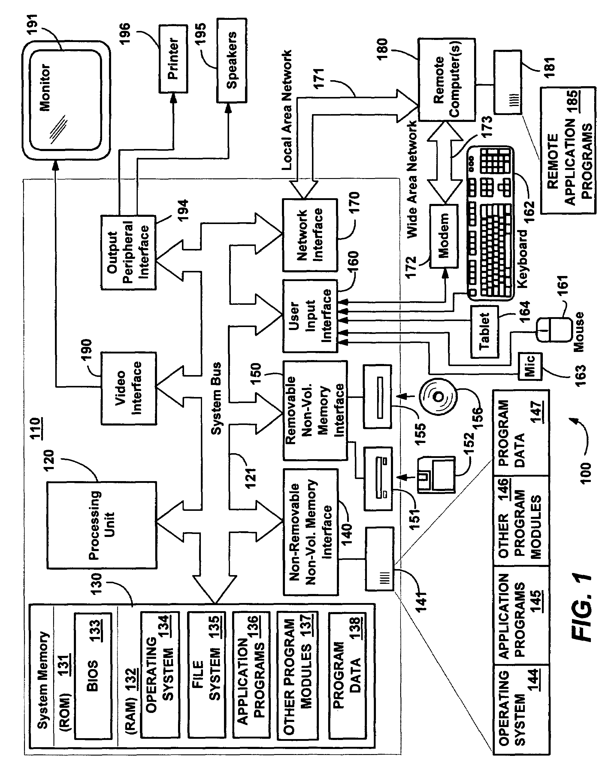
FIELD OF THE INVENTION[0001]The invention relates generally to computer systems, and more particularly to the processing of graphical and other video information for display on computer systems.BACKGROUND OF THE INVENTION[0002]The limits of the traditional immediate mode model of accessing graphics on computer systems are being reached, in part because memory and bus speeds have not kept up with the advancements in main processors and / or graphics processors. In general, the current (e.g., WM_PAINT) model for preparing a frame requires too much data processing to keep up with the hardware refresh rate when complex graphics effects are desired. As a result, when complex graphics effects are attempted with conventional graphics models, instead of completing the changes that result in the perceived visual effects in time for the next frame, the changes may be added over different frames, causing results that are visually and noticeably undesirable.[0003]A new model for controlling graph...

Claims


Application Information

Patent Timeline
Patent Type & Authority Patents(United States)
IPC IPC(8): G09G5/00G06FG06F3/14G06F19/00G06T13/00G06T13/80
CPCG06F9/545G06T13/00G06T17/005G06F3/14G06T2210/08G06T2210/61G09G2340/04G09G2340/0407G09G2340/0414G09G2340/0421G09G2340/0428G09G2340/0464G09G5/00
Inventor SUBRAMANIAN, SRIRAMBLANCO, LEONARDO E.CURTIS, DONALD B.BEDA, JOSEPH S.SCHNEIDER, GERHARD A.SCHECHTER, GREG D.SMITH, ADAM M.VANDENBERG, ERIC S.CALKINS, MATTHEW W.GALLO, KEVIN T.STOKES, MICHAELGOEL, RAJAT
Owner MICROSOFT TECH LICENSING LLC
Why Eureka
Try Eureka