Spatially enhanced transform coding

a transform and coding technology, applied in the field of prediction error coding, can solve problems such as deteriorating coding performance, and achieve the effect of good overall representation of image blocks

Active Publication Date: 2011-12-13
NOKIA TECH OY
View PDF5 Cites 2 Cited by
  • Summary
  • Abstract
  • Description
  • Claims
  • Application Information

AI Technical Summary

Benefits of technology

[0011]Various embodiments of the present invention provide a system and method for representing the prediction error signal as a weighted sum of different basis functions of a selected transform and quantized spatial samples. The basis functions of the selected transform may comprise an orthogonal set of basis vectors, or the basis functions may not comprise an orthogonal set. According to various embodiments, the prediction error signal for a single image block is constructed using both transform basis functions and spatial samples (i.e., pixel values), thereby combining the desired features of both the transform and spatial coding approaches discussed previously. This allows for the utilization of those selected transform basis functions that give good overall representation of the image block with minimal amount of transform coefficients (representing the component of prediction error signal that is well correlated with the basis functions). Additionally, various embodiments of the present invention allow for the efficient spatial representation of those components of the prediction error signal of the same image block that are not well correlated with the basis functions of the applied transform (such as certain types of sensor noise, high frequency texture and edge information).
[0014]The implementations of various embodiments of the present invention serve to improve the compression efficiency of modern video and image codecs. Although a certain amount of increased computational complexity of encoding may be needed, fast algorithms can be applied in order to lower the encoding complexity that approaches the complexity level for traditional transform based coding. Any effect on the complexity for a decoder is negligible when implementing various embodiments of the present invention.

Problems solved by technology

However, the transform can efficiently pack energy of the prediction error signal only under certain statistics, and the coding performance deteriorates when the prediction error to be transformed becomes less correlated.

Method used


Image

  • Spatially enhanced transform coding
  • Spatially enhanced transform coding
  • Spatially enhanced transform coding

Examples


Embodiment Construction

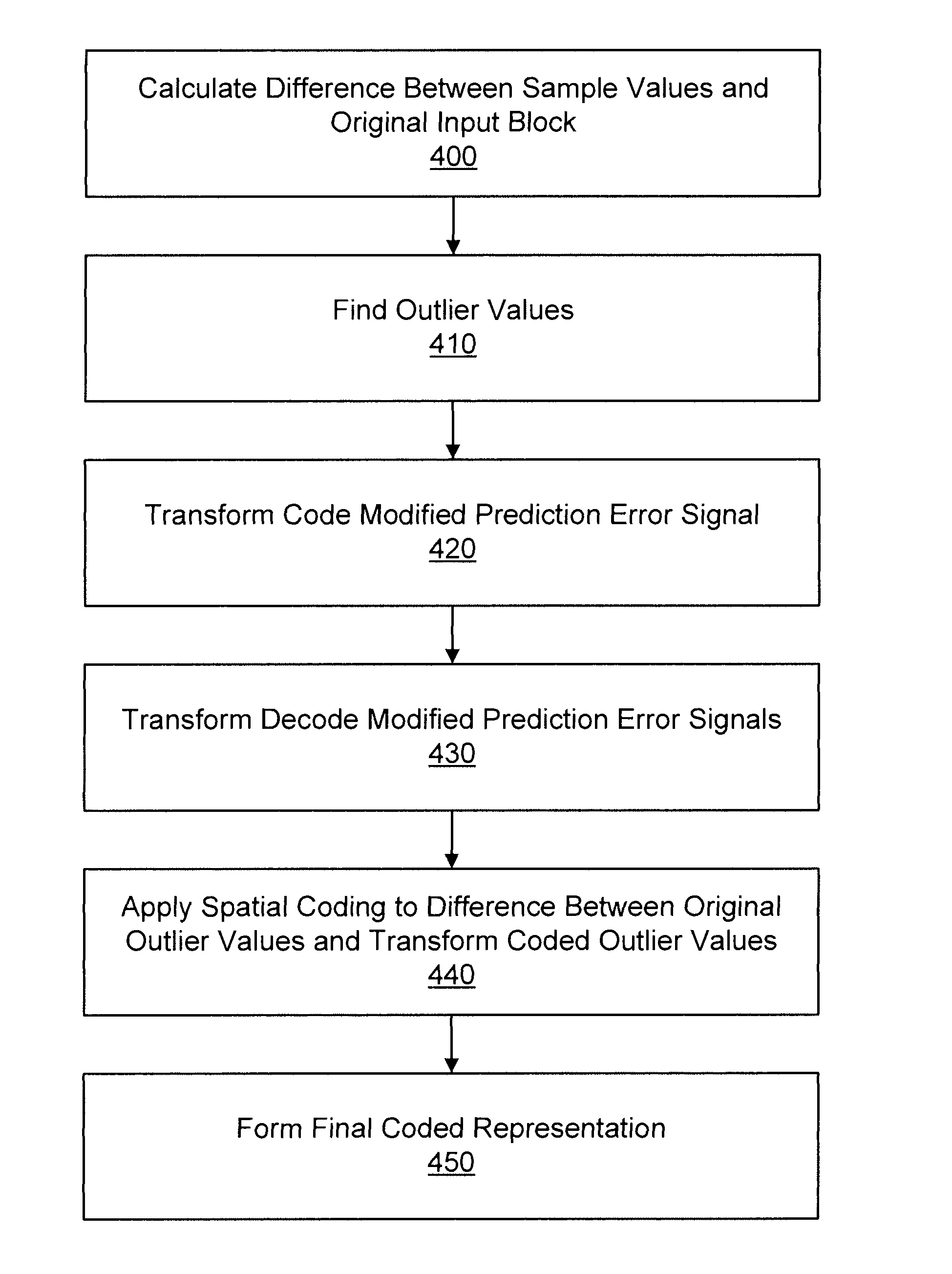
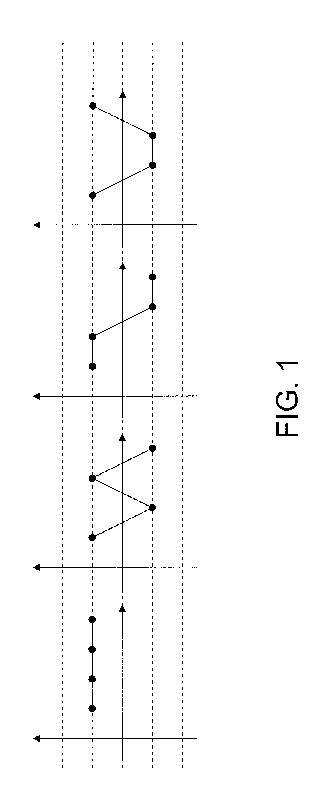
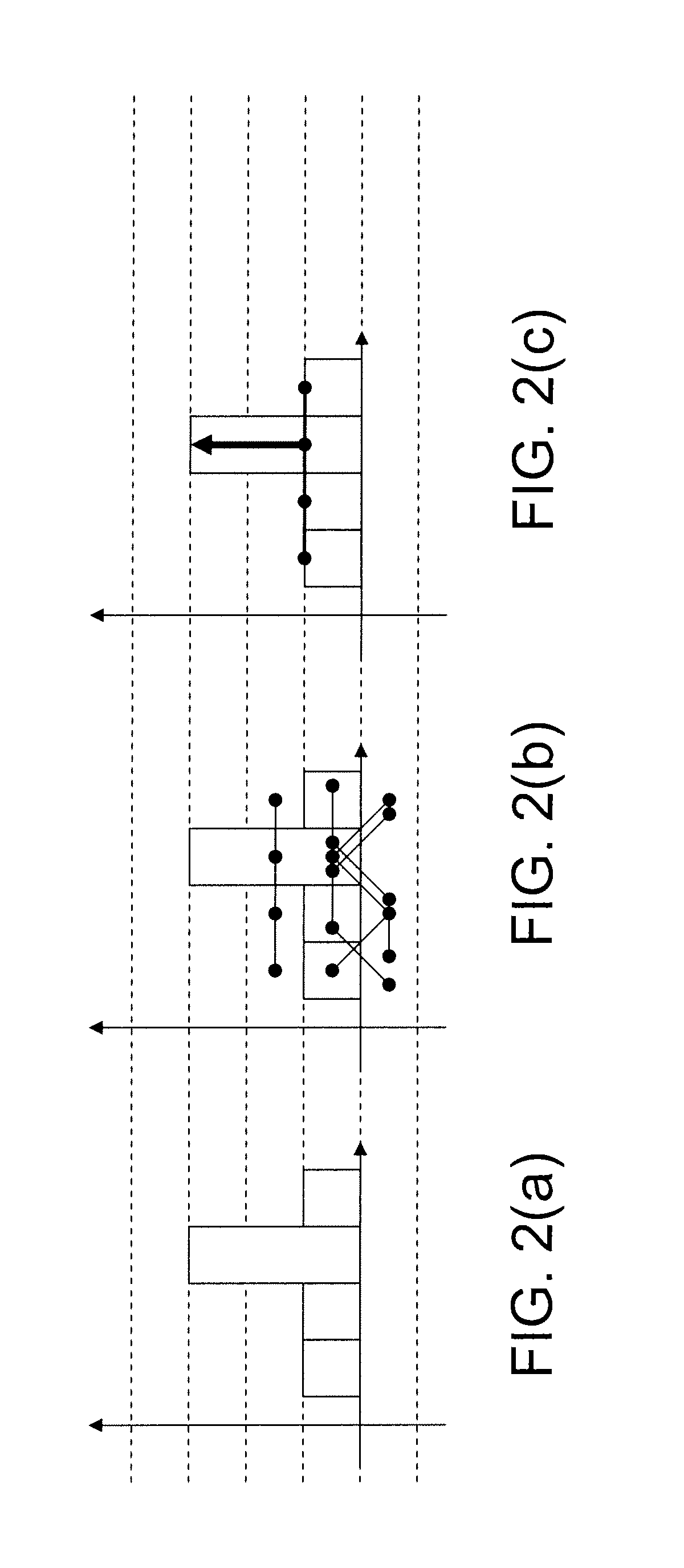
[0025]Various embodiments of the present invention provide a system and method for representing the prediction error signal as a weighted sum of different basis functions of a selected transform and quantized spatial samples. According to various embodiments, the prediction error signal for a single image block is constructed using both transform basis functions and spatial samples (i.e., pixel values), thereby combining the desired features of both the transform and spatial coding approaches discussed previously. This allows for the utilization of those selected transform basis functions that give good overall representation of the image block with minimal amount of transform coefficients (representing the component of prediction error signal that is well correlated with the basis functions). Additionally, various embodiments of the present invention allow for the efficient spatial representation of those components of the prediction error signal of the same image block that are no...


PUM


Abstract

A system and method for improving prediction error coding performance of various video compression algorithms. Various embodiments combine the energy compaction features of transform coding with localization properties of spatial coding. In various embodiments, the effects of pixel “outliers” are removed from the transform and are coded separately as a spatially coded pixel prediction, thereby improving the coding gain of the transform.

Description

FIELD OF THE INVENTION[0001]The present invention relates to the coding and decoding of digital video material. More particularly, the present invention relates to prediction error coding in both frequency and spatial domains.BACKGROUND OF THE INVENTION[0002]This section is intended to provide a background or context to the invention that is recited in the claims. The description herein may include concepts that could be pursued, but are not necessarily ones that have been previously conceived or pursued. Therefore, unless otherwise indicated herein, what is described in this section is not prior art to the description and claims in this application and is not admitted to be prior art by inclusion in this section.[0003]A video codec comprises an encoder that transforms input video into a compressed representation suited for storage and / or transmission and a decoder that can uncompress the compressed video representation back into a viewable form. Typically, the encoder discards some...

Claims


Application Information

Patent Timeline
Patent Type & Authority Patents(United States)
IPC IPC(8): G06K9/46H04N19/593H04N19/89
CPCH04N19/122H04N19/85H04N19/80H04N19/61H04N19/55H04N19/14H04N19/60
Inventor LAINEMA, JANI
Owner NOKIA TECH OY
Why Eureka
Try Eureka