
Capsule-type medical apparatus

a medical device and capsule technology, applied in the field of capsule-type medical devices, can solve the problems of difficult reuse and consumption of electric energy in the battery, and achieve the effects of improving observation functionality, convenient power-supply switching, and convenient reus

Inactive Publication Date: 2009-03-31
OLYMPUS CORP
View PDF11 Cites 134 Cited by
  • Summary
  • Abstract
  • Description
  • Claims
  • Application Information

AI Technical Summary

Benefits of technology

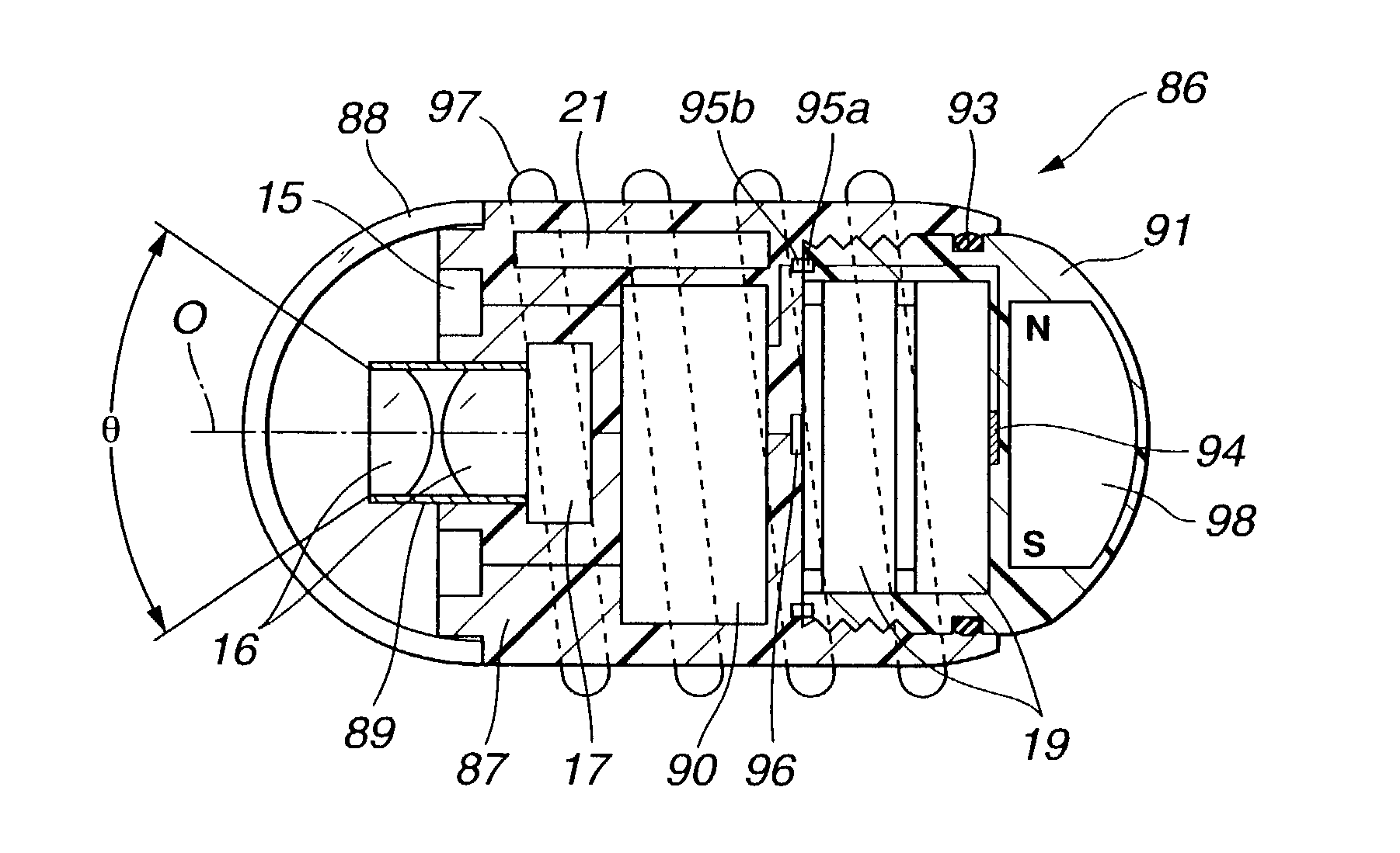
[0010]Accordingly, it is an object of the present invention to provide a capsule-type medical apparatus, which is easy to reuse by replacing a battery or a battery peripheral portion.
[0011]It is another object of the present invention to provide a capsule-type medical apparatus, which allows the easy power-supply switching.
[0012]It is another object of the present invention to provide a capsule-type endoscope, which can improve the observation functionality by the revolution thereof in a body cavity.
[0013]Accordingly, there is provided a capsule-type medical apparatus, including a capsule body portion having an imaging device for imaging and an illuminating device for illumination, a power-supply portion, which is separate from the capsule body portion and self-contains a battery, and a removable mechanism having a water-tight internal portion, which is achieved by attaching the power-supply portion to the capsule body portion. Thus, the capsule-type medical apparatus can be reused easily by replacing the battery or the power-supply portion.

Problems solved by technology

Thus, when the capsule endoscope is reused after it is swallowed by the patient once for the internal examination, the electric energy in the battery may be consumed.
As a result, it is difficult to reuse.

Method used


Image

  • Capsule-type medical apparatus
  • Capsule-type medical apparatus
  • Capsule-type medical apparatus

Examples


first embodiment

[0042]A first embodiment of the present invention will be described with reference to FIGS. 1 to 7.

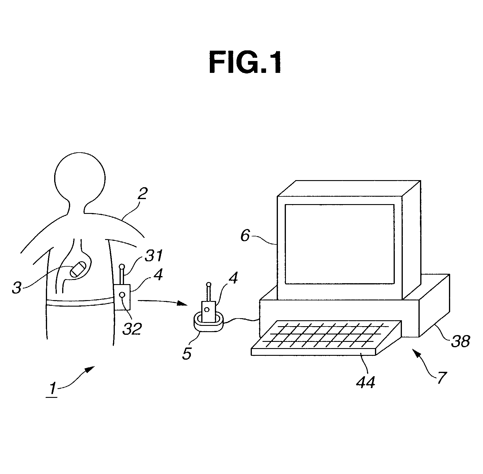
[0043]As shown in FIG. 1, a capsule endoscope system 1 includes a capsule endoscope 3 for examining the inside of a body of a patient 2, an external unit 4 for receiving image data from the capsule endoscope 3 and for storing the image data, an external unit attaching portion 5, which allows the external unit 4 to be attached removably, and a display system 7 for reading signal data stored in the external unit 4 and for displaying it in a display device 6.

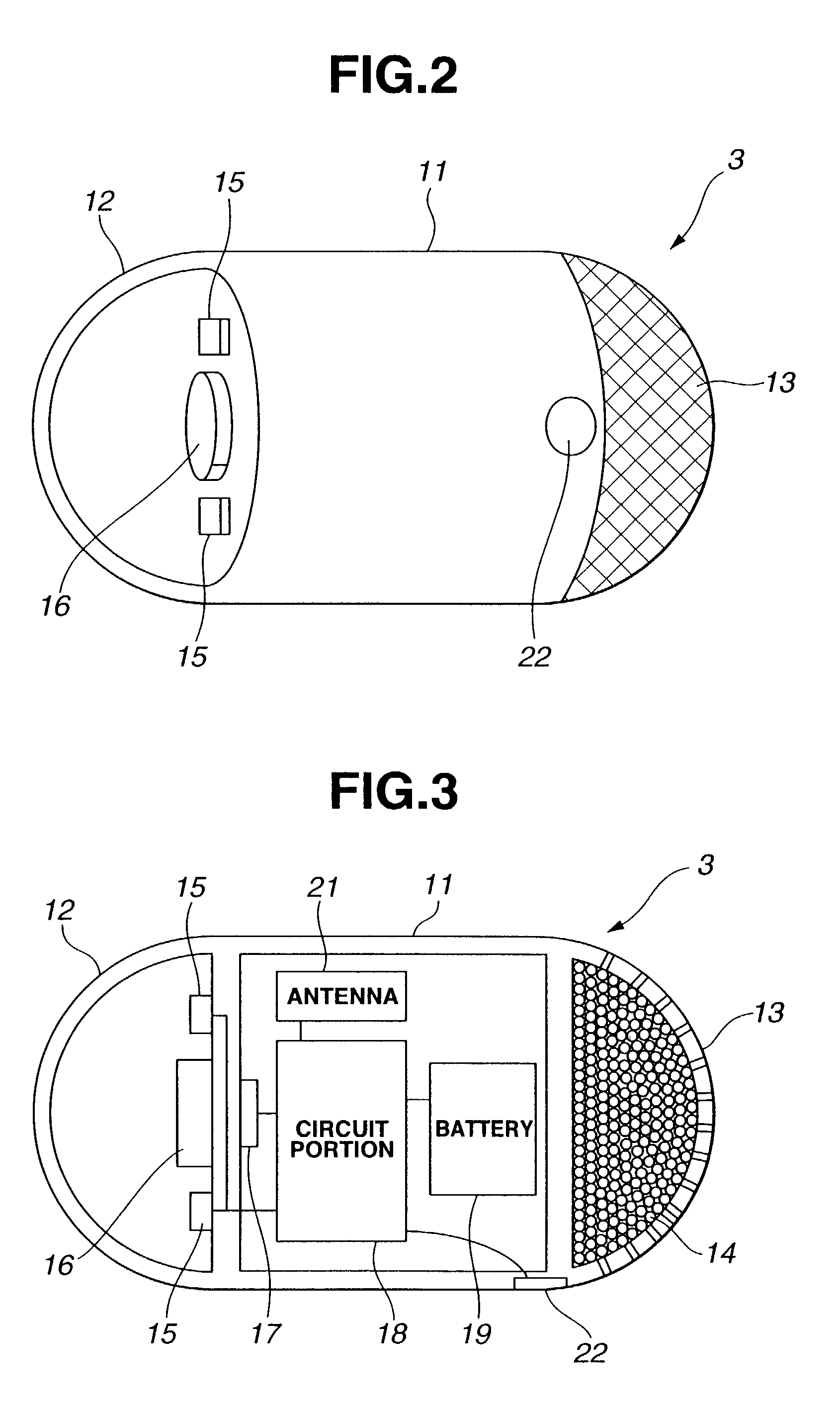
[0044]As shown in FIGS. 2 and 3, the capsule endoscope 3 is in a capsule form, which is a cylinder having both ends in a hemisphere form.

[0045]More specifically, as shown in FIG. 3, the capsule endoscope 3 has a capsule frame body 11, which is in a cylinder form having both ends being closed. One of the end surfaces of the capsule frame body 11 is in a domical form covered with a hemisphere transparent member 12 and accommodates an il...

second embodiment

[0095]A second embodiment of the present invention will be described with reference to FIGS. 8A to 13. FIGS. 8A and 8B show a capsule endoscope 3C according to the second embodiment of the present invention. FIG. 8A shows a front view of the capsule endoscope 3C, which is viewed from the front side. FIG. 8B shows a perspective view of the capsule endoscope 3C, which is viewed from the substantial side. FIG. 8C shows the internal construction of a microcapsule accommodating portion.

[0096]While the capsule endoscope 3 shown in FIGS. 2 and 3 has the illuminating and imaging units in the axis direction, the capsule endoscope 3C shown in FIGS. 8A and 8B has them in the perspective direction, which is slanted with respect to the axis direction.

[0097]In other words, the front end side of a cylinder capsule frame body 11 is cut diagonally. Then, a capsule frame body 11 is attached to an objective lens 16 at the center of the part closed by a place frame (base) 11a. The LED's 15 for illumina...

third embodiment

[0116]Next, a third embodiment of the present invention will be described with reference to FIGS. 14A to 21. FIG. 14A shows a longitudinal section of a capsule endoscope 3G according to the third embodiment. FIG. 14B shows an exploded view of the capsule endoscope 3G. The capsule endoscope 3G according to this embodiment has a double construction, and the inside portion can be reused.

[0117]As shown in FIGS. 14A and 14B, the capsule endoscope 3G has a capsule body 61, a transparent cover 62 for covering the side and the front portions of the capsule body 61, and a back cover 63 for covering a part near the rear end and the rear side part of the capsule body 61.

[0118]The capsule body 61 is in a substantial columnar form. An objective lens 16 is mounted at the center of the front end side by using a lens frame. Multiple LED's 15 are located on the peripheral in the circumference direction.

[0119]A CMOS imager 17 is located at the focus position of the objective lens 16. A driver 26 ther...


PUM


Abstract

A battery self-containing body, which self-contains a battery or a battery accommodating body, which accommodates a battery removably is attached to a capsule body including a drive circuit for driving an imaging device and an illuminating device. Thus, the power supply can be turned ON easily. In addition, the inside portion is sealed water-tightly. Thus, the battery self-containing body or a battery can be exchanged easily, which allows the easy reuse. The direction of the visual field of the imaging device is diagonal with respect to the axis of the capsule body. Furthermore, spiral-shape projections are provided on the peripheral surface of the cylinder form. Thus, the rotation allows the surface of canal cavity wall to be examined easily.

Description

[0001]This application claims benefit of Japanese Application No. 2001-229951 filed on Jul. 30, 2001, the contents of which are incorporated by this reference.BACKGROUND OF THE INVENTION[0002]1. Field of the Invention[0003]The present invention relates to a capsule-type medical apparatus for examining the inside of a body cavity, for example.[0004]2. Description of the Related Art[0005]Recently, an endoscope for observing and / or diagnosing the inside of a body cavity by inserting a long and narrow inserting portion has been widely used.[0006]On the other hand, a capsule endoscope for observing the depths within a body cavity is disclosed in Japanese Patent Application 2001-95755, for example. The disclosed capsule endoscope is in form of capsule to be swallowed by a patient, which alleviates pain felt by the patient.[0007]According to the capsule endoscope of the related art, a battery provided within a capsule container is used as a power supply to illuminate a subject by using an ...

Claims


Application Information

Patent Timeline
Patent Type & Authority Patents(United States)
IPC IPC(8): H04N7/18G02B23/24A61B1/00A61B1/04A61B5/07
CPCA61B1/00105A61B1/00158A61B1/041H04N7/185A61B2019/2253A61B34/73
Inventor TAKIZAWA, HIRONOBUADACHI, HIDEYUKIMIZUNO, HITOSHIYABE, HISAOMORIYAMA, HIROKI
Owner OLYMPUS CORP
Learn More