Gigabit ethernet passive optical network having double link structure

a passive optical network and gigabit ethernet technology, applied in data switching networks, frequency-division multiplexes, transmission monitoring, etc., can solve the problems of large time consumption and inability to perform communication, and achieve the effect of minimizing data loss and recovering quickly from link errors

Inactive Publication Date: 2009-03-31
SAMSUNG ELECTRONICS CO LTD
View PDF14 Cites 2 Cited by
  • Summary
  • Abstract
  • Description
  • Claims
  • Application Information

AI Technical Summary

Benefits of technology

[0014]Therefore, the present invention has been made in view of the above problems and provides additional advantages, by providing a GE-PON capable of readily recovering from the link failure even though a failure occurs in a single link set up between an OLT and each ONU, and a link setup method using the same.
[0015]One aspect of the present invention is to provide a GE-PON capable of rapidly recovering from the link failure than the prior art when a failure occurs in a single link set up between an OLT and each ONU, and a link setup method using the same.
[0016]Another aspect of the present invention is to provide a GE-PON which is capable of stably transmitting data while minimizing loss of the data when a failure occurs in a single link set up between an OLT and each ONU, and a link setup method using the same.
[0027]According to the teachings of the present invention, a double link having an active link and standby link is set up between an OLT and each ONU and, if there is an error in the active link, the standby link replaces the active link, thereby making it possible to more readily recover from the link error. Further, a reference time for the active link error determination is set to 10 msec at minimum, thereby minimizing data loss resulting from the link error.

Problems solved by technology

As a result, if a failure occurs in the link set up between the OLT 10 and each of the ONUs 20, 22 and 24, it is impossible to perform the communication and requires a large amount of time to recover from the link failure.

Method used


Image

  • Gigabit ethernet passive optical network having double link structure
  • Gigabit ethernet passive optical network having double link structure
  • Gigabit ethernet passive optical network having double link structure

Examples


Embodiment Construction

[0036]Now, preferred embodiments of the present invention will be described in detail with reference to the annexed drawings. In the drawings, the same or similar elements are denoted by the same reference numerals even though they are depicted in different drawings. For the purposes of clarity and simplicity, a detailed description of known functions and configurations incorporated herein will be omitted as it may make the subject matter of the present invention unclear.

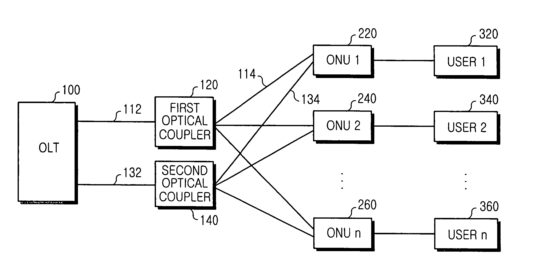
[0037]Referring to FIG. 3, a preferred embodiment of a Gigabit Ethernet passive optical network to address a link failure according to the present invention is illustrated. As shown, the Gigabit Ethernet passive optical network (GE-PON) includes an OLT 100, a plurality of ONUs 220, 240 and 260, and first and second optical couplers 120 and 140. The OLT 100 and each of the ONUs 220, 240 and 260 are interconnected by optical cables via the first and second optical couplers 120 and 140.

[0038]In operation, the OLT 100 s...


PUM


Abstract

A Gigabit Ethernet passive optical network (GE-PON) having a double link structure is disclosed. The GE-PON includes an optical line terminal (OLT), a plurality of optical couplers, and a plurality of optical network units (ONUs). The OLT sets up an active link and a standby link in response to a registration request message received over an optical cable. Each of the ONUs is doubly connected with the OLT via the optical cable and is adapted to transmit the registration request message to the OLT, form the active link with the OLT via the optical cable if it receives an active registration message transmitted from the OLT in response to the registration request message, and form the standby link with the OLT via the optical cable if it receives a standby message from the OLT. The optical couplers are disposed between the OLT and each of the ONUs to doubly interconnect them via different optical cables.

Description

CLAIM OF PRIORITY[0001]This application claims priority to an application entitled “GIGABIT ETHERNET PASSIVE OPTICAL NETWORK HAVING DOUBLE LINK STRUCTURE,” filed in the Korean Intellectual Property Office on Aug. 26, 2003 and assigned Serial No. 2003-59015, the contents of which are hereby incorporated by reference.BACKGROUND OF THE INVENTION[0002]1. Field of the Invention[0003]The present invention relates to a Gigabit Ethernet passive optical network (GE-PON) having an optical line terminal (OLT) and a plurality of optical network units (ONUs) and, more particularly, to a GE-PON having a double link structure to address a link failure between the OLT and each ONU, and a double link method using the same.[0004]2. Description of the Related Art[0005]A passive optical network (PON) is a communication network that transfers signals to end users over an optical cable network. The PON consists of a single OLT installed in a communication facility and a plurality of ONUs installed nearby...

Claims


Application Information

Patent Timeline
Patent Type & Authority Patents(United States)
IPC IPC(8): H04B10/08H04L12/26H04L12/28H04L1/22H04L12/56H04Q11/00
CPCH04L1/22H04L49/352H04Q11/0067H04L49/357H04Q11/0066H04Q2011/0081H04L12/28
Inventor LEE, MIN-HYOKIM, YOUNG-SEOKOH, YUN-JEPARK, TAE-SUNG
Owner SAMSUNG ELECTRONICS CO LTD
Why Eureka
Try Eureka