Split-cycle aircraft engine

a technology of aircraft engines and cylinders, which is applied in the direction of machines/engines, positive displacement engines, mechanical equipment, etc., can solve the problems of noisy conventional radial engines, affecting the flight of aircraft, and consuming more oil than other engine designs, so as to reduce the friction between the piston and the seat, and increase the torque of the engin

Inactive Publication Date: 2009-04-07
SKADERI GRUP LLC
View PDF8 Cites 29 Cited by
  • Summary
  • Abstract
  • Description
  • Claims
  • Application Information

AI Technical Summary

Benefits of technology

[0019]In another embodiment of the present invention, a split-cycle horizontally opposed (i.e., “boxer”) engine that may be used for aircraft applications is provided. A split-cycle horizontally opposed engine allows for the power cylinders to fire once per revolution of the crankshaft rather then every other revolution and allows the compression cylinders to compress charge air during every revolution of the crankshaft. The split-cycle horizontally opposed engine also allows for the compression cylinders to operate with a larger diameter in comparison to the power cylinders to increase the volume of air inhaled into the engine, allowing for supercharging of the engine without the use of an external supercharger.
[0021]In yet another embodiment of the present invention, a split-cycle radial engine that may be used for aircraft applications is provided. A split-cycle radial engine allows for sequential firing of the cylinders, which increases the torque of the engine. A split-cycle radial engine also allows for offsetting of the engine cylinders relative to the crankshaft, further increasing the torque of the engine and reducing piston-skirt friction. Moreover, a split-cycle radial engine is capable of inhaling larger volumes of charge intake air, which improves the performance of the engine at high altitudes where the air is thinner.

Problems solved by technology

Conventional radial engines tend to be noisy and to consume more oil than other engine designs.
Also, conventional radial engines have mechanical issues such as oil draining into the lower cylinders during non-use of the engine.
This oil must be removed from the cylinders by turning the engine over by hand prior to starting the engine, which is an inconvenience to the pilot or the ground crew.
Horizontally opposed engines, however, are often noisier than other engine configurations such as V-type engines and inline engines.
Also, horizontally opposed engines can be more difficult to fit into an engine compartment because horizontally opposed engines tend to be wider than other engine configurations.
However, conventional aircraft lack a convenient and efficient source of compressed air, thereby rendering these potential uses of compressed air infeasible.

Method used


Image

  • Split-cycle aircraft engine
  • Split-cycle aircraft engine
  • Split-cycle aircraft engine

Examples


Embodiment Construction

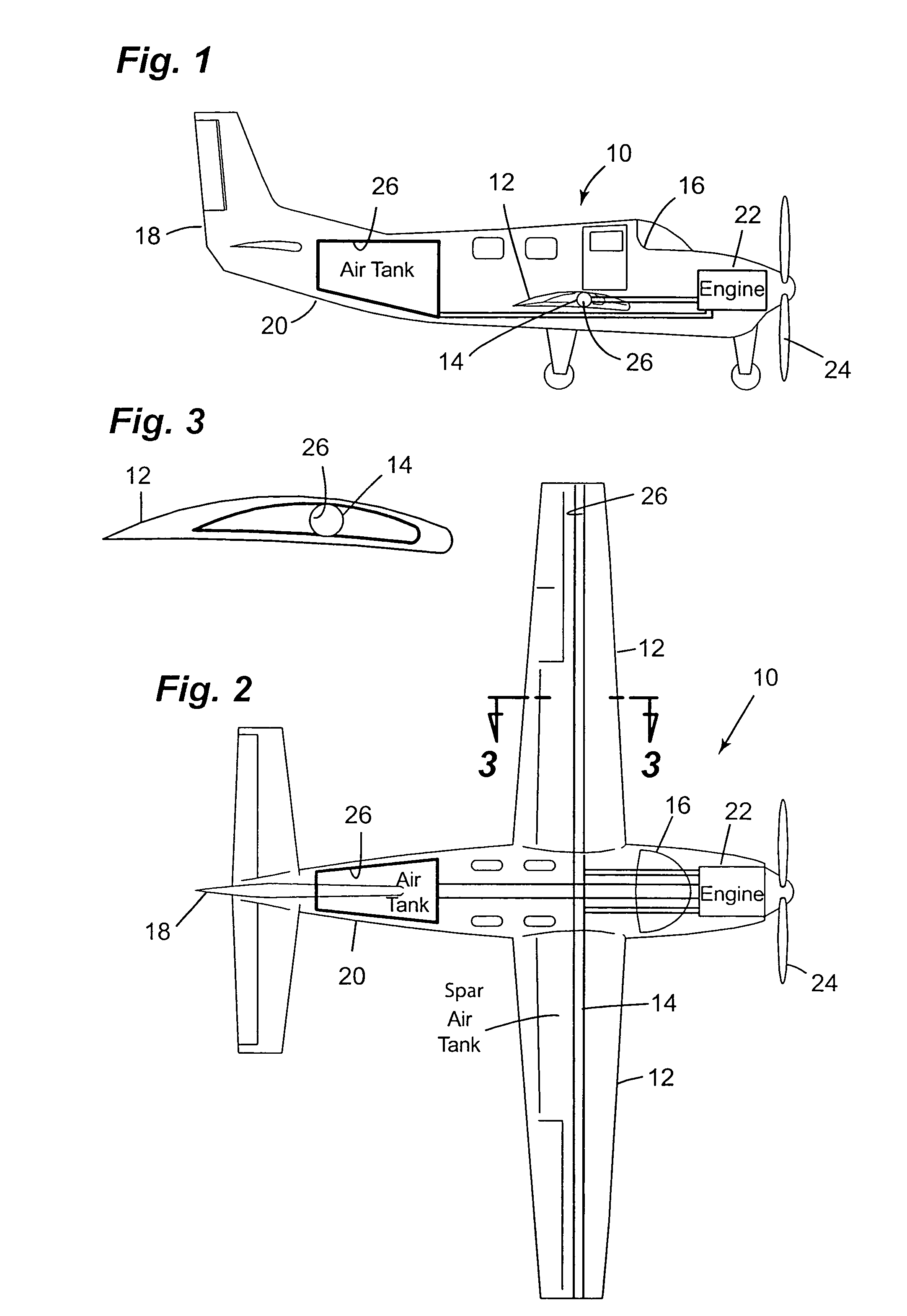
[0037]Referring now to the drawings in detail, numeral 10 generally indicates a propeller-driven aircraft. As illustrated in FIGS. 1 through 3, the aircraft 10 has a pair of wings 12, a wing spar 14 in the wings 12, a cockpit 16, a tail 18, and an aft fuselage 20. The aircraft 10 may have one wing spar 14 spanning both wings 12, or a separate wing spar may be located in each wing 12. A split-cycle engine 22 in accordance with the invention is mounted in the aircraft 10 forward of the cockpit 16 to drive the propeller 24. Air storage tanks 26 may be located in the wing spar 14, the aft fuselage 20, or both. The air storage tank(s) may also be located in any other suitable location within the aircraft 10, for example, in a suitable location within the wings 12 other than the wing spar 14.

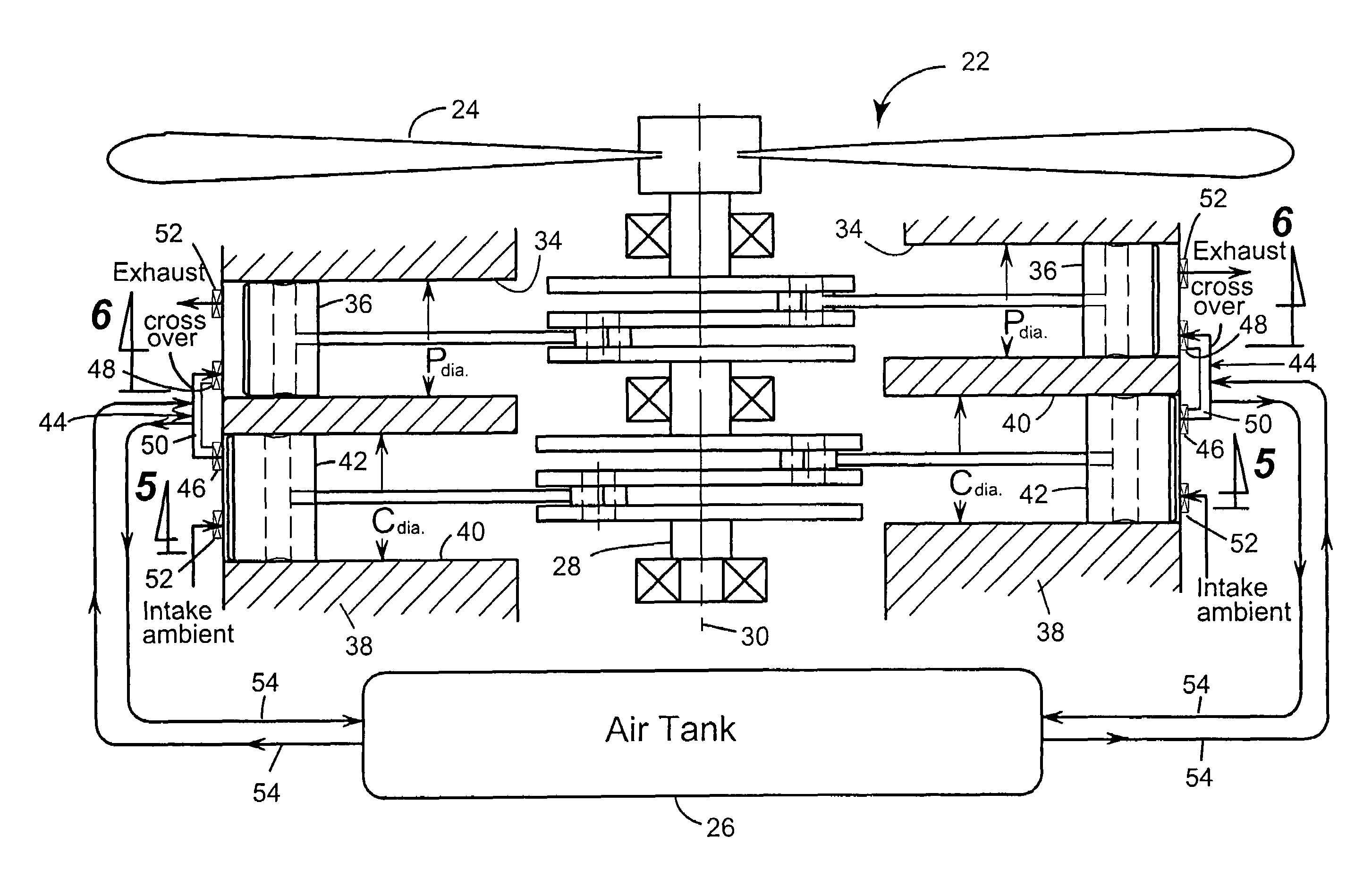
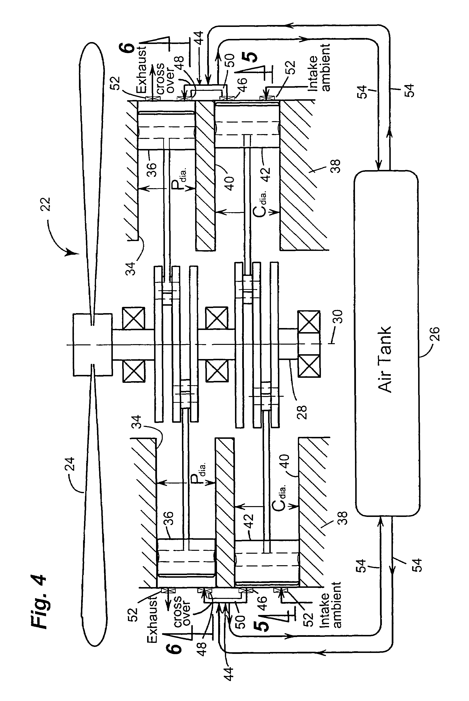
[0038]Turning first to FIGS. 4 through 9, in one embodiment of the invention, the split-cycle engine 22 may be a horizontally opposed (“boxer”) type split-cycle engine. The split-cycle boxer engine 22...


PUM


Abstract

A split-cycle aircraft engine includes a crankshaft rotatable about a crankshaft axis. A power piston is slidably received within a power cylinder and is operatively connected to the crankshaft such that the power piston reciprocates through an expansion stroke and an exhaust stroke during a single rotation of the crankshaft. A compression piston is slidably received within a compression cylinder and is operatively connected to the crankshaft such that the compression piston reciprocates through an intake stroke and a compression stroke during a single rotation of the crankshaft. A gas crossover passage operatively interconnects the compression cylinder and the power cylinder. An air reservoir is operatively connected to the gas crossover passage by a reservoir passage. The air reservoir is selectively operable to receive and deliver compressed air. The engine is mounted to an aircraft and the air reservoir is disposed within the aircraft.

Description

TECHNICAL FIELD[0001]This invention relates to split-cycle engines, and more particularly to split-cycle aircraft engines.BACKGROUND OF THE INVENTION[0002]The term split-cycle engine as used in the present application may not have yet received a fixed meaning commonly known to those skilled in the engine art. Accordingly, for purposes of clarity, the following definition is offered for the term split-cycle engine as may be applied to engines disclosed in the prior art and as referred to in the present application.[0003]A split-cycle engine as referred to herein comprises:[0004]a crankshaft rotatable about a crankshaft axis;[0005]a power piston slidably received within a power cylinder and operatively connected to the crankshaft such that the power piston reciprocates through a power (or expansion) stroke and an exhaust stroke during a single rotation of the crankshaft;[0006]a compression piston slidably received within a compression cylinder and operatively connected to the cranksha...

Claims


Application Information

Patent Timeline
Patent Type & Authority Patents(United States)
IPC IPC(8): F01B7/12
CPCB64D27/24F01B17/025F02B59/00F02B69/00B64D2027/026Y02T50/44Y02T50/64Y02T50/60Y02T50/40F02B75/24F02G3/00B64D27/20
Inventor HEATON, CLIFFORD D.
Owner SKADERI GRUP LLC
Why Eureka
Try Eureka