LED lighting apparatus

a technology of led lighting and lighting apparatus, which is applied in the direction of lighting and heating apparatus, applications, instruments, etc., can solve the problems of complex configuration of lighting apparatus, inability to appropriately adjust the irradiation direction and position of light, etc., and achieve the effect of brighter illumination

Inactive Publication Date: 2009-04-07
SHARP KK
View PDF7 Cites 8 Cited by
  • Summary
  • Abstract
  • Description
  • Claims
  • Application Information

AI Technical Summary

Benefits of technology

[0010]According to this LED lighting apparatus of the present invention, LED light is repeatedly reflected by the inner periphery of the rod-like light-guiding body and gradually diffuses when passing through the rod-like light-guiding body, which means that diffused light exits from the upper end of the rod-like light-guiding body, and the light reflected by the light reflector is also diffused. This diffused light does not feel glary. Also, since the irradiation direction and range is specified by the reflection of the light reflector, efficient illumination is possible.
[0013]Moreover, all that need be provided is a base, an LED, a rod-like light-guiding body and a light reflector, thereby avoiding a complex configuration.
[0016]These configurations allow the irradiation direction and range of the light to be clearly specified in the case of mirror reflection, and the irradiation range of the light to be broadened in the case of diffuse reflection. The choice of configuration can be made according to the primary usage of the lighting apparatus.
[0017]Also, the LED lighting apparatus may further include plural pairs of the LED and the rod-like light-guiding body, and in each pair, light from the LED may exit from the upper end of the rod-like light-guiding body and be reflected by the light reflector. This configuration enables brighter illumination.

Problems solved by technology

With this sort of lighting apparatus, glare is a problem when looking directly at that the LEDs, making it necessary to reduce glare.
However, even if the LED light is irradiated through a translucent white diffuser, enabling glare to be reduced, it is not possible to appropriately adjust the irradiation direction and position of the light.
Also, even if the use of a plurality of reflective mirrors as in patent document 1 enables the irradiation direction and position of the light to be adjusted, the configuration of the lighting apparatus become complex.

Method used


Image

  • LED lighting apparatus
  • LED lighting apparatus
  • LED lighting apparatus

Examples


first embodiment

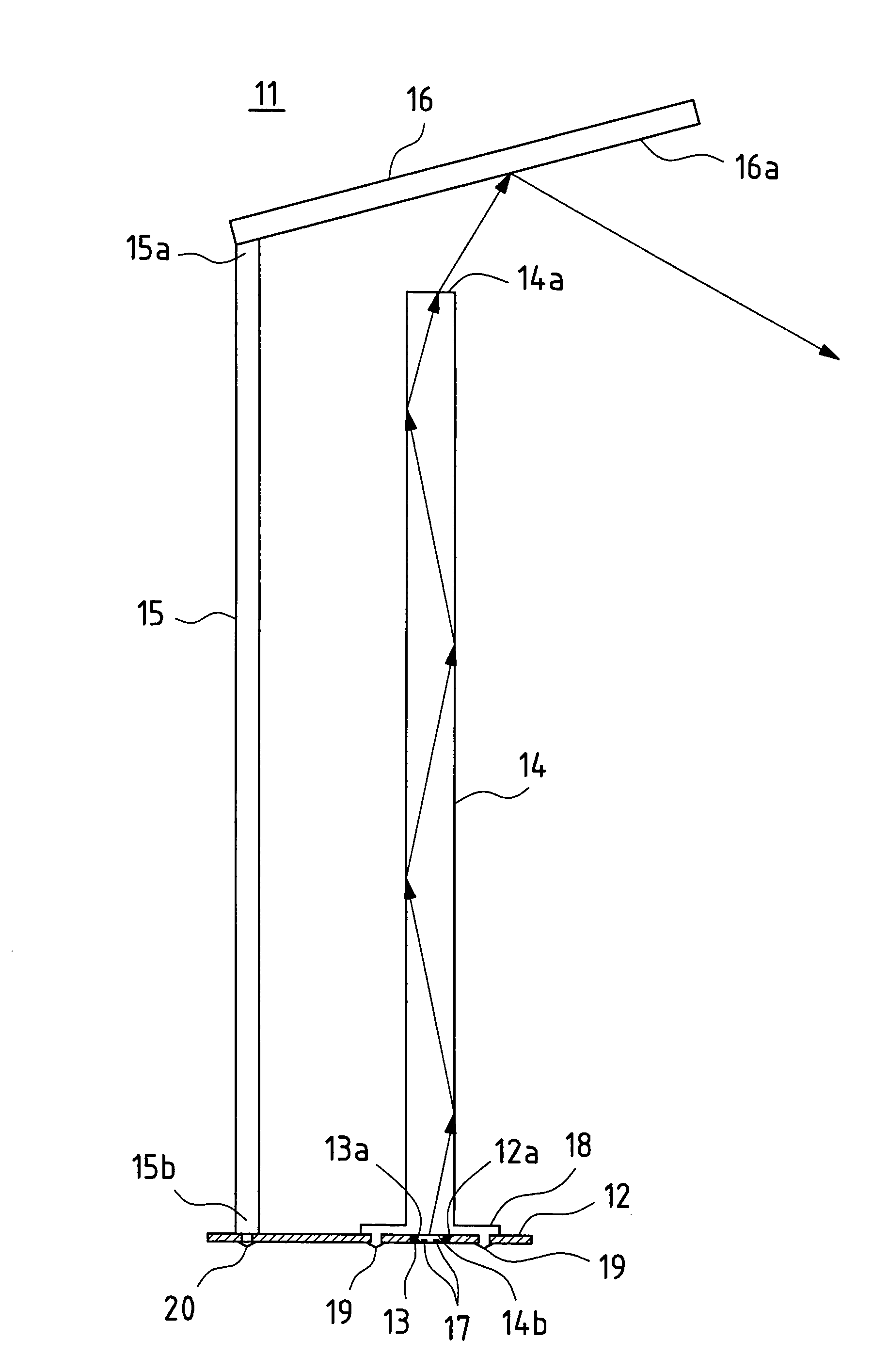
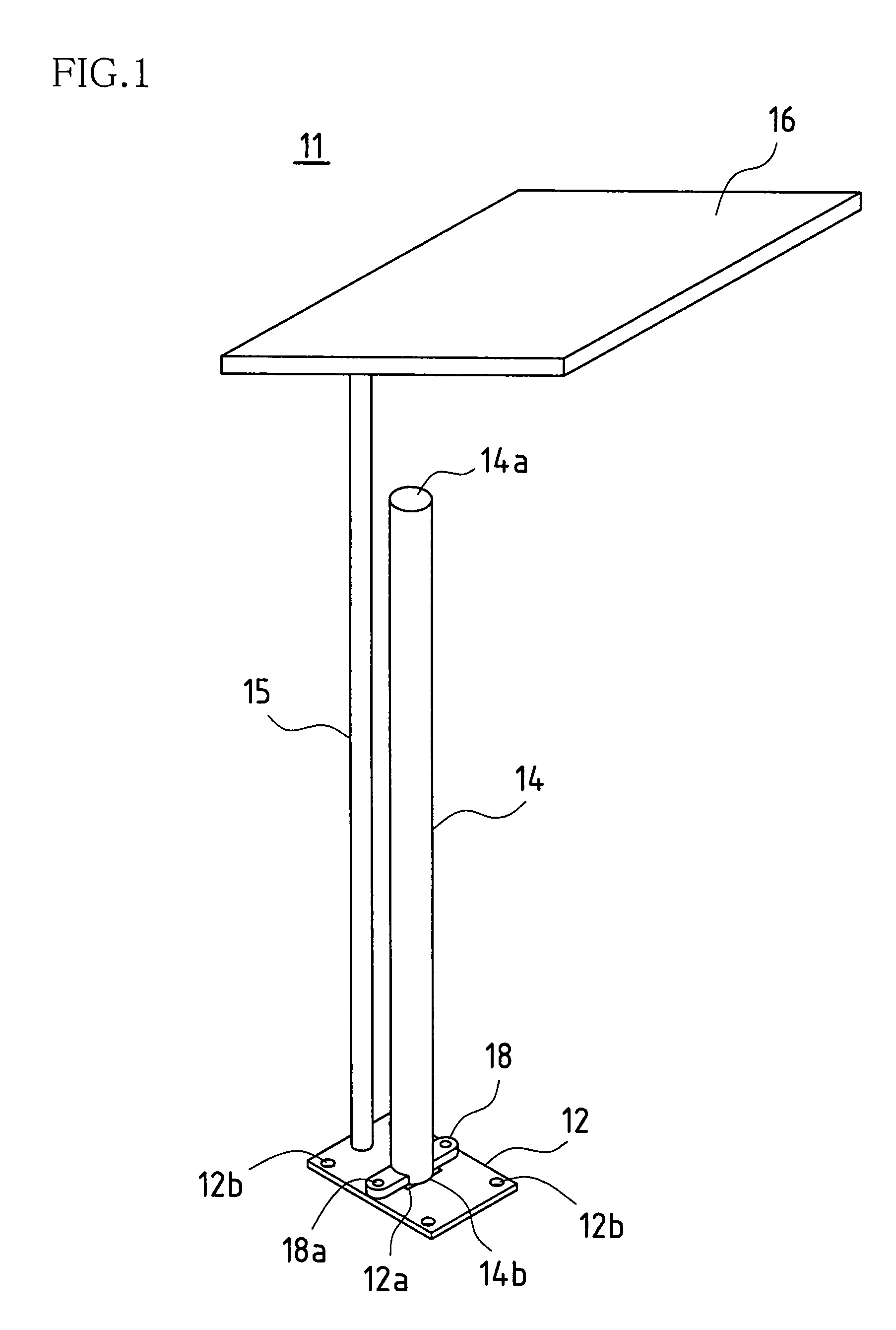
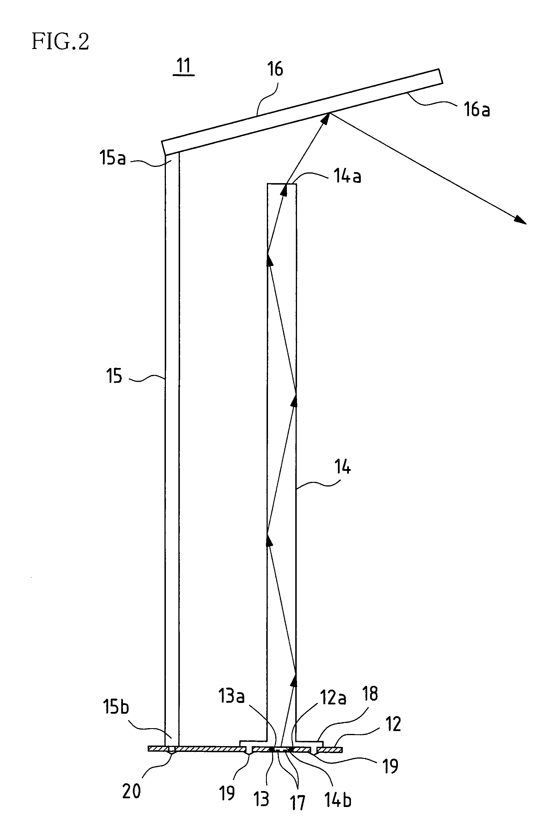
[0042]FIGS. 1 and 2 are a perspective view and a cross-sectional view showing an LED lighting apparatus of the present invention. The LED lighting apparatus 11 of the present embodiment includes a tabular base 12 fixed to the floor, a light source unit 13 disposed in a rectangular hole 12a in the middle of the tabular base 12, a rod-like light-guiding body 14 protruding up from the tabular base 12 where the light source unit 13 is positioned, a strut 15 protruding up from the tabular base 12 so as to be parallel with the rod-like light-guiding body 14, and a reflector 16 fixed to an upper end 15a of the strut 15 above an upper end 14a of the rod-like light-guiding body 14.

[0043]A small hole 12b is formed in each of the four corners of the tabular base 12 as shown in FIGS. 3 and 4. The tabular base 12 is placed on the floor, and screws (not shown) are screwed into the floor through the small holes 12b to fix the tabular base 12 to the floor.

[0044]The rectangular hole 12a is formed in...

second embodiment

[0053]FIGS. 5 and 6 are a perspective view and a cross-sectional view showing the LED lighting apparatus of the present invention. Note that in FIGS. 5 and 6, the same reference numerals are attached to sites that perform a similar action to FIGS. 1 and 2.

[0054]The LED lighting apparatus 21 of the present embodiment includes a tabular base 22 fixed to the floor, three light source units 13 disposed in three holes 22a formed in the tabular base 22, three rod-like light-guiding bodies 14 protruding up from the tabular base 22 where the light source units 13 are positioned, a strut 25 protruding up from the tabular base 22 in the middle of the rod-like light-guiding bodies 14, and an inverted conical reflector 26 fixed to an upper end 25a of the strut 25 above the upper ends 14a of the rod-like light-guiding bodies 14.

[0055]Consequently, the LED lighting apparatus 21 has three pairs of the light source unit 13 and the rod-like light-guiding body 14.

[0056]The tabular base 22 is placed o...


PUM


Abstract

An LED lighting apparatus includes an LED provided on a base, a rod-like light-guiding body having translucency that protrudes from the base, and a light reflector disposed in a vicinity of an upper end of the rod-like light-guiding body. Light from the LED is incident on a lower end of the rod-like light-guiding body, exits from the upper end via the rod-like light-guiding body, and is reflected by the light reflector.

Description

BACKGROUND OF THE INVENTION[0001]This application claims priority under 35 U.S.C. § 119(a) on Patent Application No. 2007-085365 filed in Japan on Mar. 28, 2007, the entire content of which is herein incorporated by reference.[0002]The present invention relates to an LED lighting apparatus suitable for table lighting, ambient lighting and the like.[0003]A table lamp 101 as shown in FIG. 21 and an interior light 102 as shown in FIG. 22 are examples of lighting apparatuses that use LEDs (light emitting diodes) as the light source.[0004]With this sort of lighting apparatus, glare is a problem when looking directly at that the LEDs, making it necessary to reduce glare. With the interior light 102 in FIG. 22, for example, you look straight at the light source of the interior light 102 when you look up, making it desirable to reduce glare. The LED light is therefore irradiated through a translucent white diffuser, for example, thereby reducing glare.[0005]It is preferable not only to redu...

Claims


Application Information

Patent Timeline
Patent Type & Authority Patents(United States)
IPC IPC(8): F21V33/00H01L33/58H01L33/60
CPCF21S6/003F21S6/005F21V7/0008F21S6/00F21V2200/13F21Y2101/02Y10S362/80F21Y2115/10G02B6/0008
Inventor ISHIKURA, TAKUROFUJIYAMA, YUTAKA
Owner SHARP KK
Why Eureka
Try Eureka