Electrical connection box

a technology of electrical connection box and fuse block, which is applied in the direction of electrical apparatus casing/cabinet/drawer, gaseous cathode, coupling device connection, etc., can solve the problem of difficult to restrict and achieve the effect of restricting the rocking of the fuse block

Active Publication Date: 2009-04-07
AUTONETWORKS TECH LTD +2
View PDF21 Cites 21 Cited by
  • Summary
  • Abstract
  • Description
  • Claims
  • Application Information

AI Technical Summary

Benefits of technology

[0006]The mutual engagement of the rocking restricting portions that are provided on the frame side edge portion and the arm portion restricts displacement of the arm portion in relation to the frame side edge ...

Problems solved by technology

However, it is difficult to restrict rocking of the fu...

Method used


Image

  • Electrical connection box
  • Electrical connection box
  • Electrical connection box

Examples


example 1

ILLUSTRATIVE EXAMPLE 1

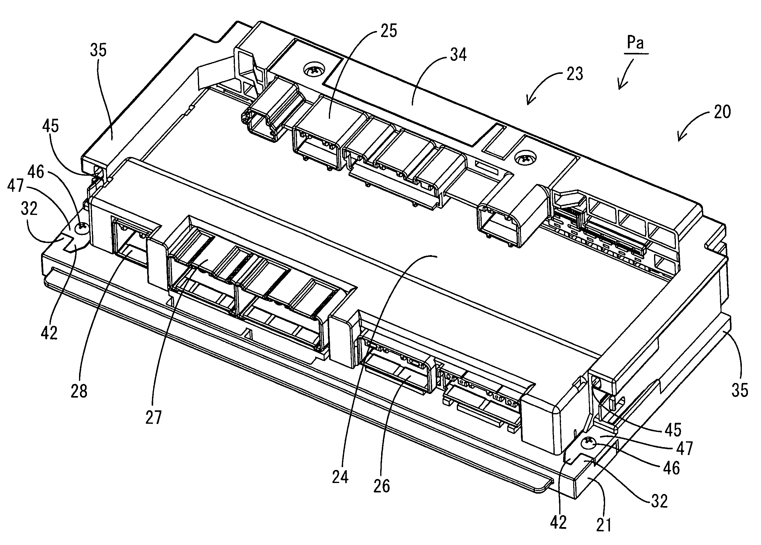
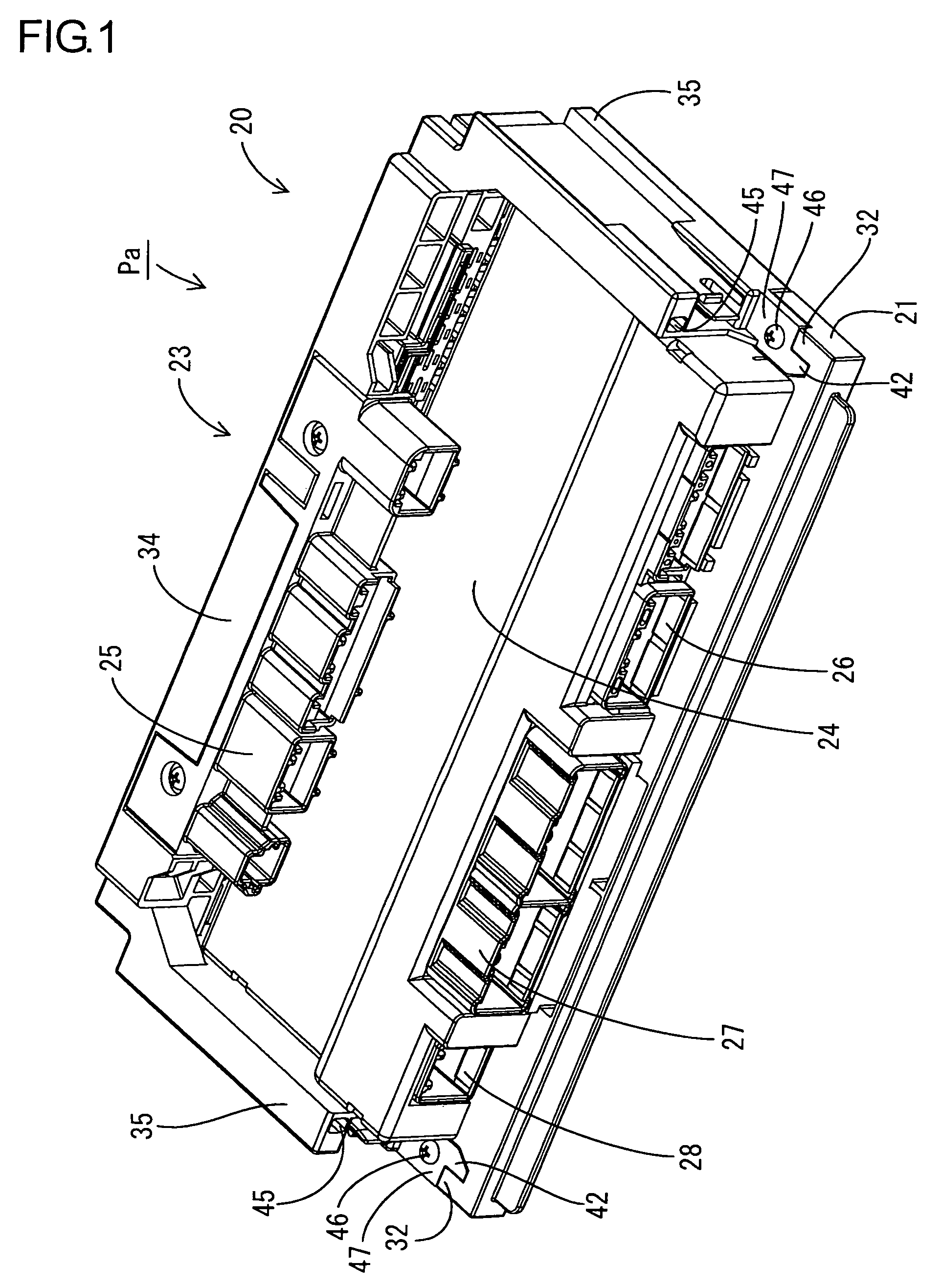
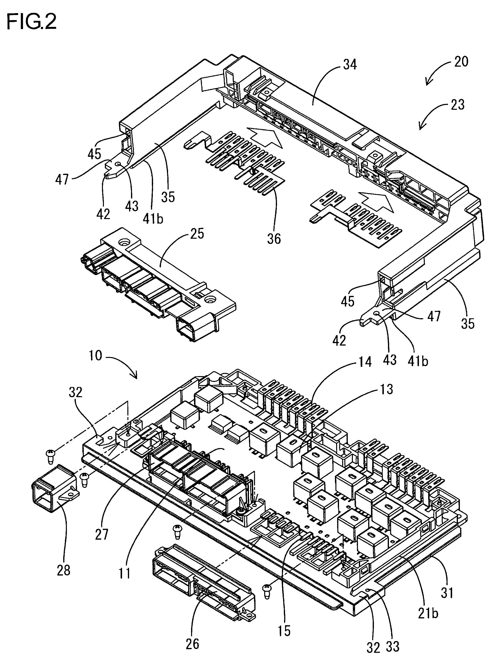
[0036]Illustrative example 1, which embodies the present invention, is explained with reference to FIG. 1 through FIG. 6. In this illustrative example, an electrical connection box Pa is mounted in an automobile, positioned between a battery (not illustrated) and electrical equipment such as lamps, audio, and the like (not illustrated). The electrical connection box Pa not only takes electric power supplied by the battery and distributes it to the electrical equipment, but also controls the switching and the like of the electric power supply to each piece of equipment. In FIG. 1 through FIG. 4, the electrical connection box Pa is drawn so that its obverse (front) side faces upward, but in its installed state in an automobile, the electrical connection box Pa is oriented such that a main body portion 34 of a fuse block 23 is positioned on the top side and arm portions 35 of the fuse block 23 extend downward. Hereinafter, the up-down and left-right orientations a...

example 2

ILLUSTRATIVE EXAMPLE 2

[0054]Illustrative example 2, which embodies the present invention, is explained with reference to FIG. 7 through FIG. 11. In illustrative example 2, an electrical connection box Pb has a configuration in which the bottom end portions of arm portions 35 and the bottom end portions of side edge portions 21b of a frame 21 are shaped differently from their counterparts in illustrative example 1. All other structures are the same as in illustrative example 1, so for the same structures, the same symbols are used, and explanations of their structures, operations, and effects are omitted.

[0055]Rib-shaped rocking restricting portions 31 are formed on the outer sides of both the left and right side edge portions 21b of the frame 21 and extend in continuous straight lines in the up-down direction (the direction parallel to the direction in which a fuse block 23 is attached to the frame 21 and parallel to the length direction of the side edge portions 21b). The rocking r...


PUM


Abstract

A fuse block 23 includes a main body portion 34, which is arranged along a top edge portion 21a of a frame 21, and an arm portion 35, which extends from an end of the main body portion 34 along a side edge portion 21b of the frame 21 that is roughly orthogonal to the top edge portion 21a. The mutual engagement of rocking restricting portions 31 and 41 that are provided on the side edge portion 21b of the frame 21 and the arm portion 35 restricts displacement of the arm portion 35 in relation to the side edge portion 21b of the frame 21 in a direction orthogonal to the length direction of the side edge portion 21b. This prevents rocking of the fuse block 23 in which the top edge portion 21a of the frame 21 serves roughly as a fulcrum.

Description

TECHNICAL FIELD[0001]The present invention relates to an electrical connection box.BACKGROUND ART[0002]Cases are known in which an electrical connection box that is mounted in an automobile has a structure in which a circuit assembly is included in a case. The circuit assembly includes a circuit board, bus bars wired into the circuit along the reverse face of the circuit board, and switching members such as relays and the like that are mounted on the obverse side of the circuit board. The case includes a roughly rectangular frame that is secured in position around a perimeter edge of the circuit board, a cover that is mounted so as to cover the circuit board from the obverse side in relation to the frame, a heat sink that is affixed to the reverse face of the circuit board and that covers the opening on the reverse side of the frame, and a long, narrow fuse block that is mounted along one side of the frame. An example of such an electrical connection box is disclosed in Patent Docum...

Claims


Application Information

Patent Timeline
IPC IPC(8): H02G3/08
CPCH02G3/086H01H2085/208Y10S439/949
Inventor SASAKI, YOSHIKAZUKITA, YUKINORI
Owner AUTONETWORKS TECH LTD
Why Eureka
Try Eureka