

Method for the construction of an induction hob, as well as an induction hob
a construction method and induction hob technology, applied in the direction of hot plate heating arrangement, electric/magnetic/electromagnetic heating, magnetic bodies, etc., can solve the problems of affecting the operation of the hot plate, and requiring a relatively long connecting cabl
- Summary
- Abstract
- Description
- Claims
- Application Information
AI Technical Summary
Benefits of technology
Problems solved by technology
Method used
Image

Examples
Embodiment Construction
[0010]One embodiment of the present invention is a method of constructing a hob having the features of claim 1 and an induction hob having the features of claim 11. Advantageous and preferred developments of the invention form the subject matter of the further claims and are explained in greater detail hereinafter. Some of the subsequently indicated features are only mentioned for the method or only for the induction hob, but independently of this can apply both to the method and the hob.
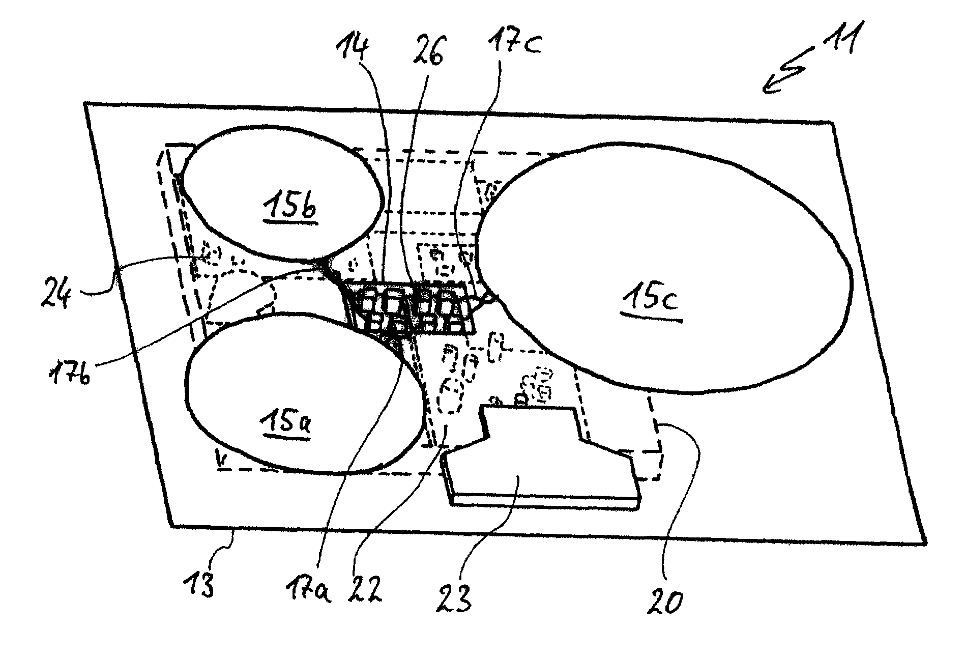
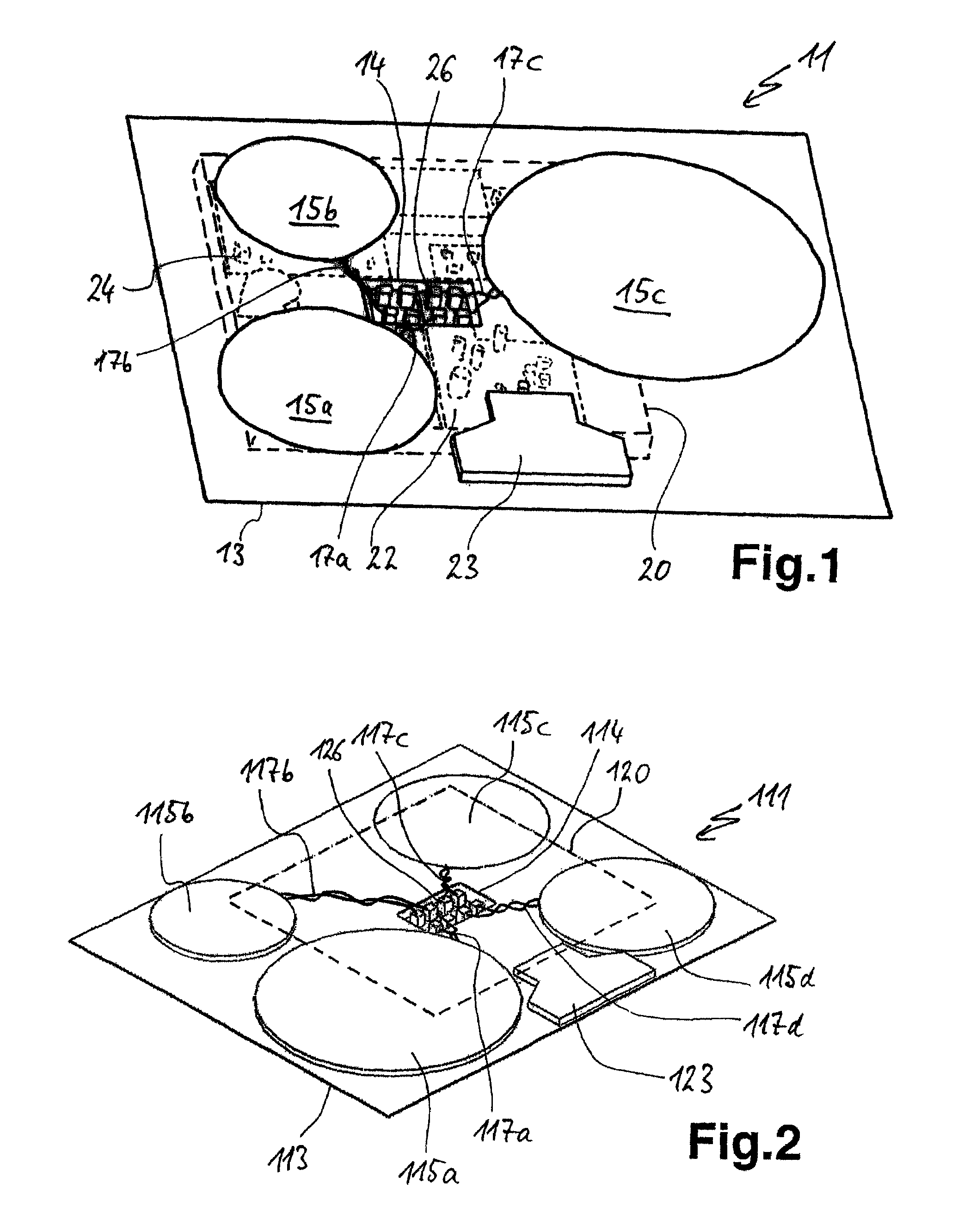
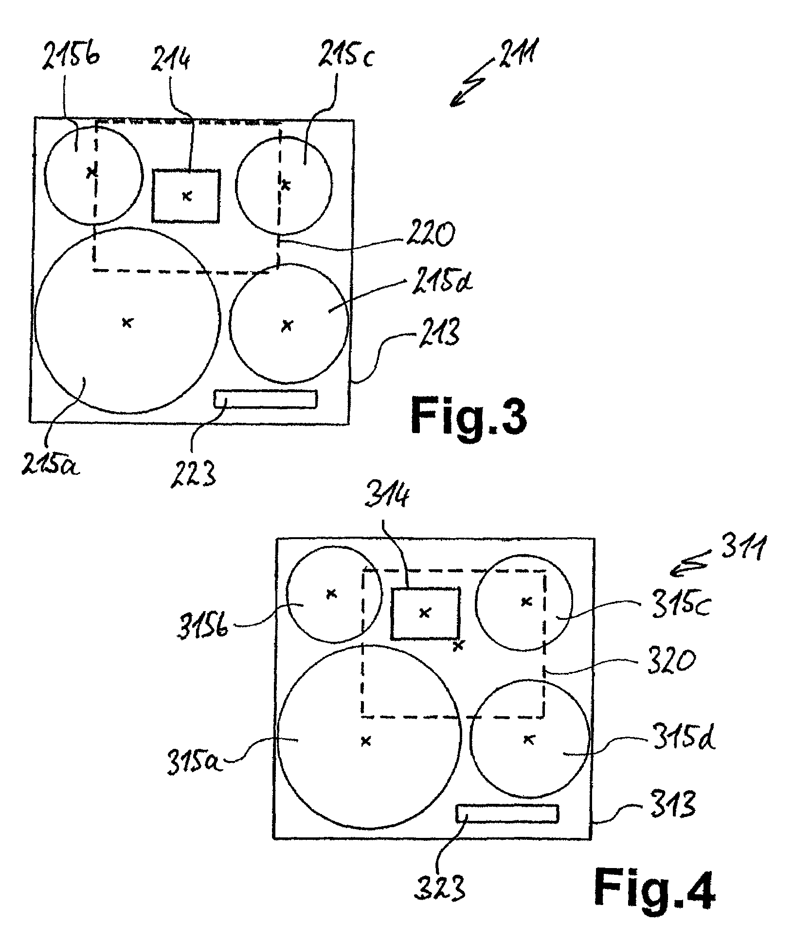
[0011]An induction hob is typically constructed with an inductor support plate on which there are at least two inductors. Beneath the inductor support plate is positioned a fixed receptacle for a control mechanism or power electronics. Through an opening or recess in the inductor support plate, the inductors are connected via connecting cables to the control mechanism or power electronics. According to the invention, during the manufacturing of the opening or recess, or the manufacture of the induct...
PUM
| Property | Measurement | Unit |
|---|---|---|
| distance | aaaaa | aaaaa |
| area | aaaaa | aaaaa |
| length | aaaaa | aaaaa |
Abstract
Description
Claims
Application Information