Radial sliding seal with subassembly for metering devices, and metering device with such a radial sliding seal subassembly

a metering device and sub-assembly technology, which is applied in the direction of functional valve types, laboratory glassware, reagent containers, etc., can solve the problems of varying the radial pretensioning force of the o-ring as the pretensioning component varies

Active Publication Date: 2015-11-10
HAMILTON BONADUZ AG
View PDF35 Cites 6 Cited by
  • Summary
  • Abstract
  • Description
  • Claims
  • Application Information

AI Technical Summary

Benefits of technology

[0016]Radial sliding seal subassemblies with very small geometrical dimensions and at the same time extremely low production and / or installation costs can be obtained if at least one radial spring segment is connected in the region of one of its axial longitudinal ends to the spring carrier and is formed with a pretensioning axial section, axially spaced from the axial longitudinal end, for contact on the pretensioning surface. In this case a radial spring segment can project in the manner of a leaf spring from the spring carrier in the axial direction and with its free longitudinal end can be springy in the radial direction with movement forms known from an idealised unilaterally clamped beam. In this connection the pretensioning axial section is provided on a radial spring segment, preferably on a region comprising the free axial longitudinal end of the radial spring segment. This need not necessarily be the case however: by suitably shaping the leaf spring-like radial spring segment an axial section lying between the axial longitudinal end connected to the spring carrier and the free axial longitudinal end of the radial spring segment can also be designed as a pretensioning axial section, so long as on the basis of this shape it is designed for contact with the pretensioning surface of the sealing component, i.e. in the installed state of the radial sliding seal subassembly it actually lies against the pretensioning surface.
[0020]In order to keep the necessary number of components for forming a radial sliding seal subassembly according to the invention as low as possible, it is advantageous if as many as possible, preferably all, radial spring segments project from the carrier section in the axial direction.
[0032]According to a further advantageous modification of the present invention the securement device in the region of the pretensioning axial section can be provided on one or more radial spring segments, so that the radial pretensioning force with which the radial spring segment presses against the sealing component increases the positional security of the sealing component and pretensioning component relative to one another.
[0037]In this connection, for an installation space-saving arrangement the clamping force generating component can in a simple manner be formed as a ring surrounding the pretensioning component at least in the region of its radial spring segments. For a better definition of the radial pretensioning force that can be generated by the clamping force generating component, a radial projection is preferably formed on the clamping force generating component formed as a ring, which projects from the clamping force generating component to the pretensioning component.

Problems solved by technology

A disadvantage of these known types of radial sliding seal subassembly is on the one hand the fact that the radial pretensioning force exerted by the O-ring as the pretensioning component varies very greatly on account of large dimensional tolerances and a large variation of the determining material properties of the known rubber-elastic pretensioning components.

Method used


Image

  • Radial sliding seal with subassembly for metering devices, and metering device with such a radial sliding seal subassembly
  • Radial sliding seal with subassembly for metering devices, and metering device with such a radial sliding seal subassembly
  • Radial sliding seal with subassembly for metering devices, and metering device with such a radial sliding seal subassembly

Examples


first embodiment

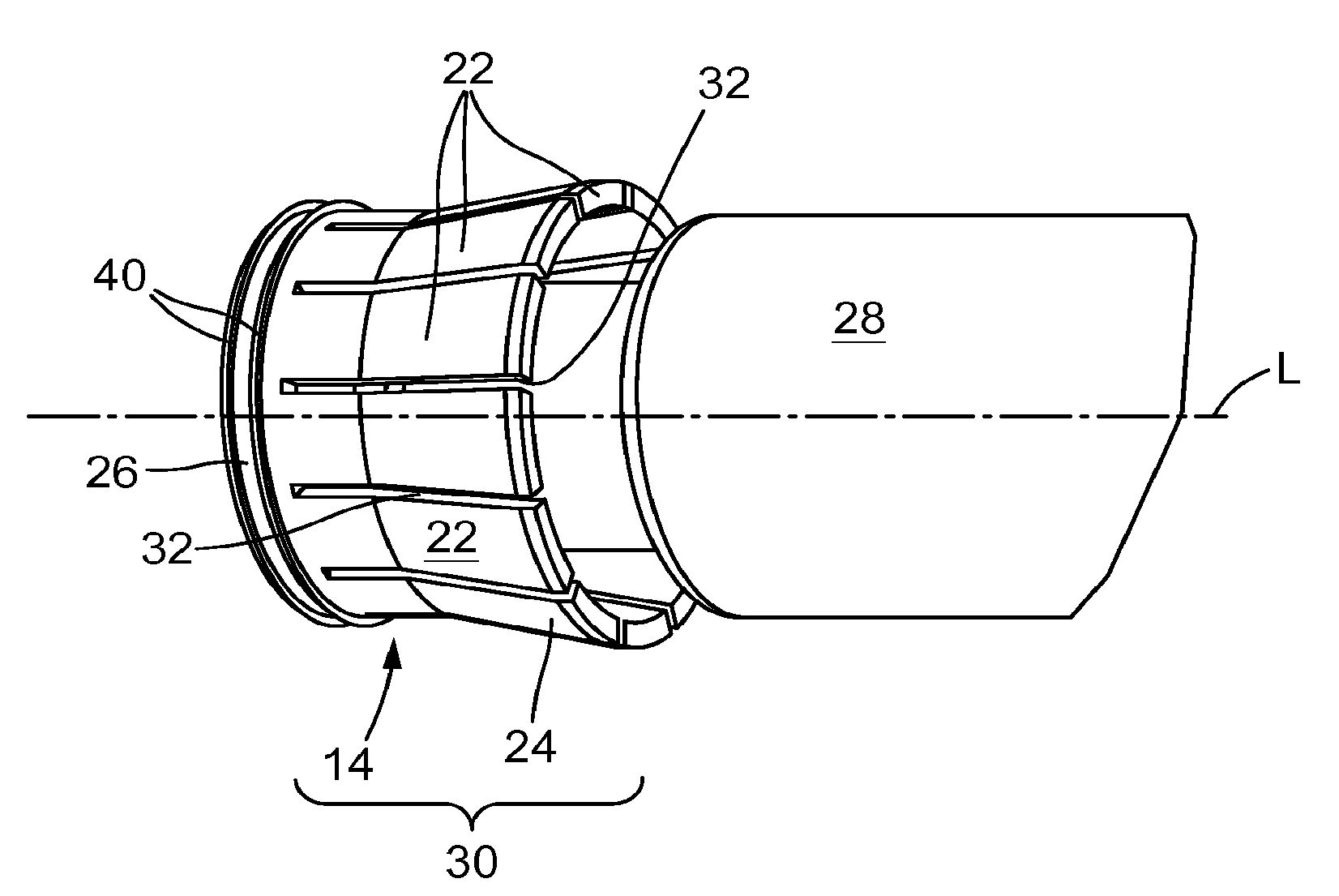
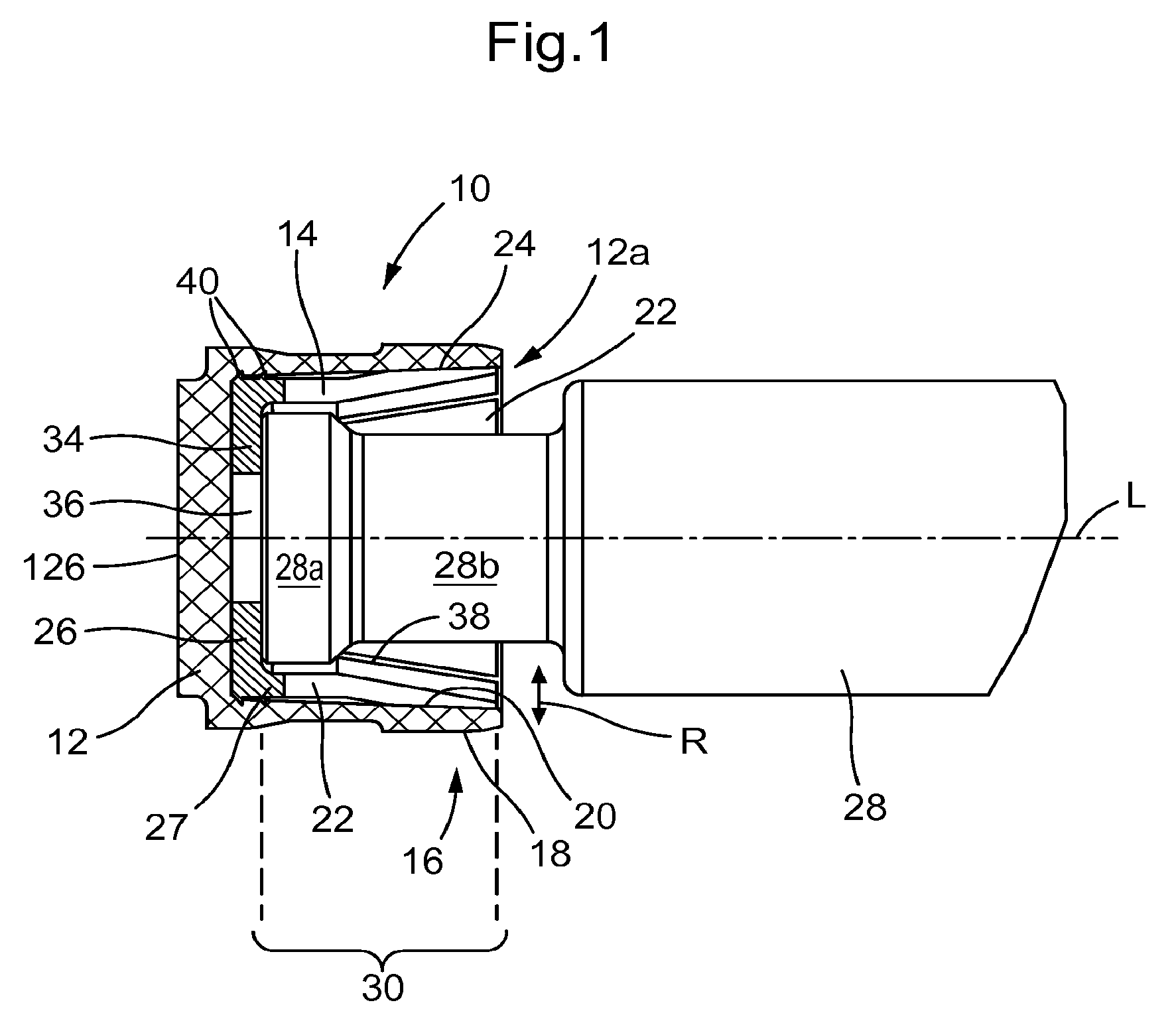
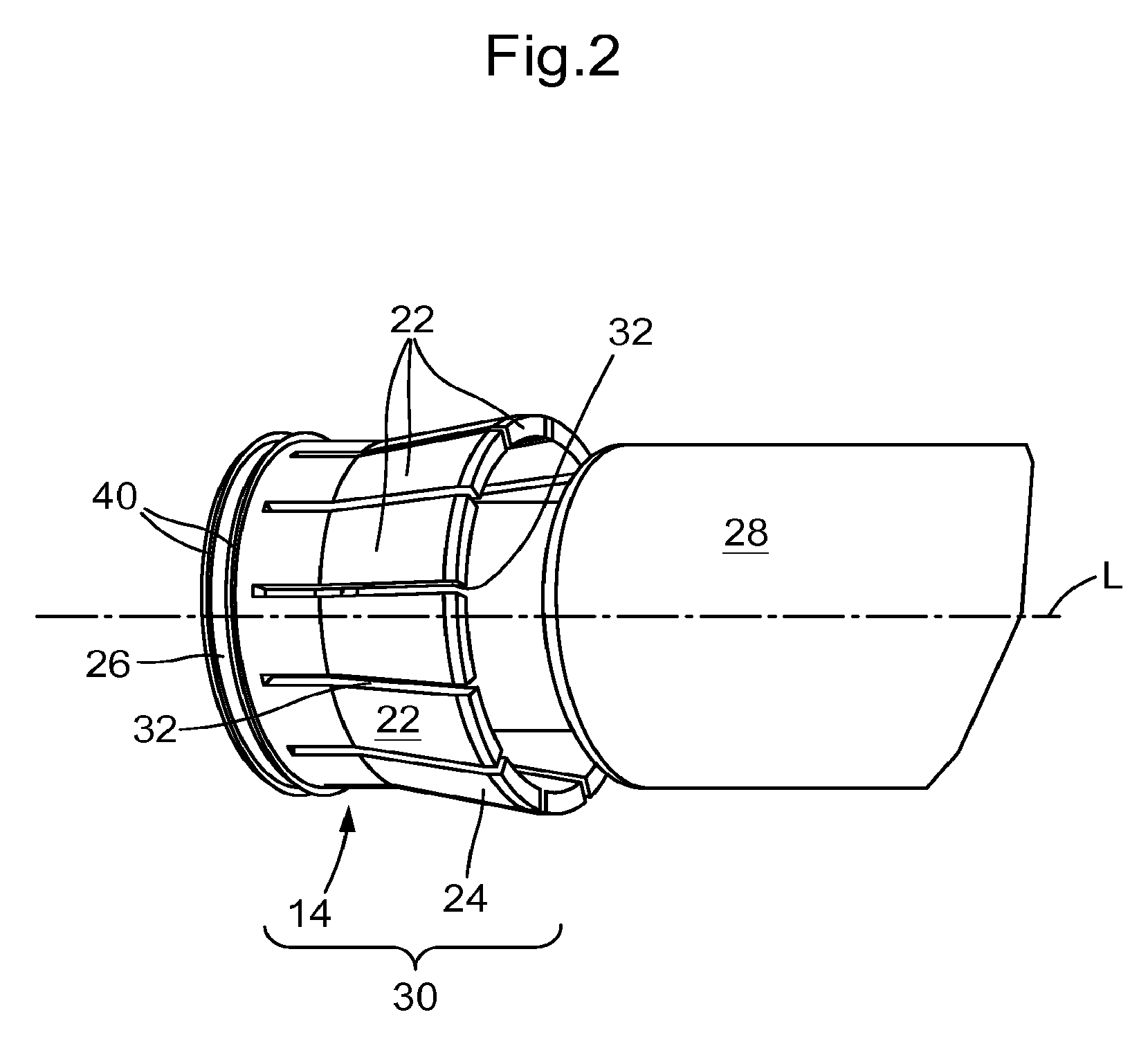
[0053]In FIG. 1 a radial sliding seal subassembly according to the invention shown in longitudinal cross-section is generally denoted by the reference numeral 10. This comprises a pot-shaped sealing component 12 that externally surrounds a pretensioning component 14.

[0054]The sealing component 12 has in the region of its open longitudinal end 12a a sealing section 16, which comprises on its radially outer side a sealing surface 18 all the way round in the circumferential direction and extending a predetermined amount in the axial direction, a pretensioning surface 20 being formed in the region of the sealing section 16 on the side facing in the radially opposite direction, on which surface rests a plurality of radial spring segments 22 each having a pretensioning axial section 24.

[0055]The pretensioning component 14 has in addition to the radial spring segments 22 a spring carrier 26, with whose carrier section 27 lying next to the radial spring segments in the axial direction the r...

second embodiment

[0066]FIG. 3 shows a radial sliding seal subassembly according to the invention in the installed state in a metering device.

[0067]Identical structural parts as in the first embodiment of FIGS. 1 and 2 are provided with the same reference numerals in the second embodiment of FIGS. 3 to 5, but in each case increased by 100. The second embodiment is discussed only insofar as it differs from the first embodiment, to the description of which reference is otherwise expressly made.

[0068]In FIG. 3 a metering device is generally denoted by the reference numeral 141. This device comprises a cylinder 142, in which a piston rod 128 is accommodated in a movable manner relative to the cylinder along the longitudinal axis L of the piston rod. The piston rod longitudinal axis L is at the same time also the longitudinal axis of the cylinder 142.

[0069]The cylinder 142 is formed in several parts, with a cylinder main body 145 and a closure and installation subassembly 146, which at the outlet side of ...

fifth embodiment

[0087]FIG. 8 is discussed hereinafter only insofar as it differs from the already described embodiments 1 and 4.

[0088]The fifth embodiment of FIG. 8 too shows a radial sliding seal subassembly with two pretensioning components 414, which are completely identical to the pretensioning components 14 and 314 respectively of the first and fourth embodiments.


PUM


Abstract

A metering device for use in syringes and pipetting piston-cylinder arrangements, including a sealing component working together with at least one pretensioning component. The sealing component comprises a sealing segment extending in the axial direction and in the circumferential direction. The sealing segment has a sealing surface facing in a first radial direction for sealing and sliding contact in at least the axial direction, is formed on a working surface formed on the outer surface of the piston rod facing toward the inner wall of the cylinder. The sealing segment also has a pretensioning surface extending in a second radial direction opposite to the first for engaging with the pretensioning component for transferring the radial pretensioning force, where the pretensioning component includes a spring carrier and a plurality of separately formed radial spring segments compliantly supported at least in the radial direction on the spring carrier.

Description

RELATED APPLICATIONS[0001]This application is a divisional of Ser. No. 13 / 127,511, U.S. Pat. No. 8,557,197; filed May 4, 2011 which is 35 U.S.C. 371 National Phase Entry Application from PCT / EP2008 / 009319, filed Nov. 5, 2008, the disclosures of which are incorporated herein in their entirety by reference.BACKGROUND OF THE INVENTION[0002]The present invention relates to a radial sliding seal subassembly with a sealing component and with at least one pretensioning component co-operating therewith, wherein the sealing component comprises a sealing section extending in the axial direction and in the circumferential direction, on which a sealing surface facing in a first radial direction is formed for sealing and at least in the axial direction sliding contact on a working surface extending in the axial direction and in the circumferential direction, and on which a pretensioning surface facing in a second radial direction opposite to the first radial direction is formed, for engagement w...

Claims


Application Information

Patent Timeline
Patent Type & Authority Patents(United States)
IPC IPC(8): B01L3/02B01L3/00F16J15/32F16J15/56F16K21/04
CPCB01L3/52B01L3/021B01L3/0217F16J15/3208F16J15/56F16K21/04
Inventor LECKEBUSCH, KLAUS
Owner HAMILTON BONADUZ AG
Why Eureka
Try Eureka