Selective power management of disk drives during semi-idle time in order to save power and increase drive life span

a disk drive and semi-idle time technology, applied in the field of storage systems, can solve the problems of wasting power, unable to keep all the disk drives in the raid array spinning up all the time, and the disk drive to fail sooner than the other way around, and achieve the effect of significant power saving and extended disk drive li

Active Publication Date: 2009-04-07
EMC IP HLDG CO LLC
View PDF8 Cites 84 Cited by
  • Summary
  • Abstract
  • Description
  • Claims
  • Application Information

AI Technical Summary

Benefits of technology

[0008]Significant power savings and extended disk drive life is obtained through implementation of the various embodiments of the invention in storage arrays.

Problems solved by technology

Such disks are not typically designed to work at a high duty cycle.
This can cause the disk drives to fail sooner than they would if used in the environment for which they were originally designed.
Furthermore, keeping all the disk drives in the RAID array spun up all the time uses relatively high power.

Method used


Image

  • Selective power management of disk drives during semi-idle time in order to save power and increase drive life span
  • Selective power management of disk drives during semi-idle time in order to save power and increase drive life span
  • Selective power management of disk drives during semi-idle time in order to save power and increase drive life span

Examples


Embodiment Construction

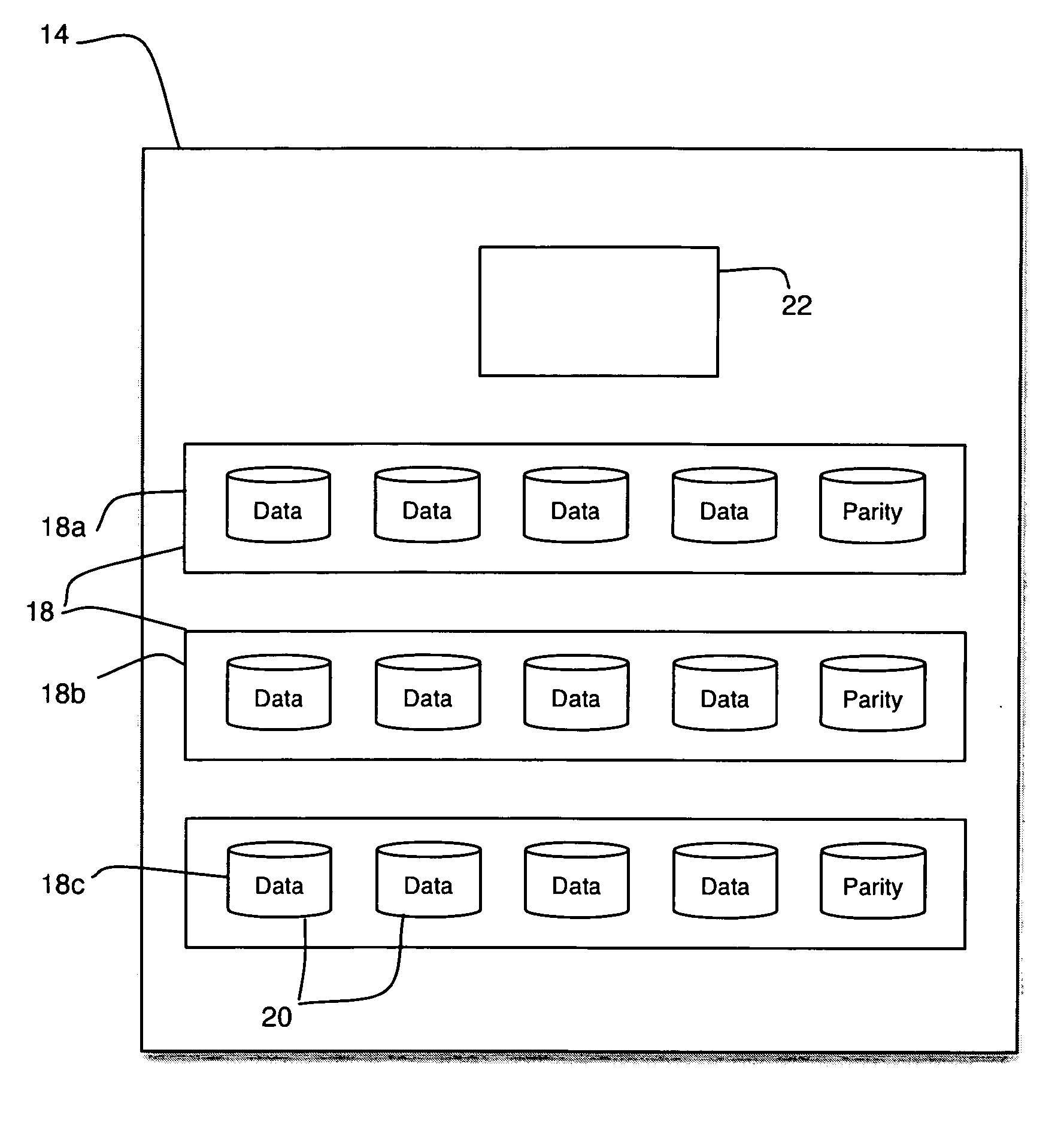
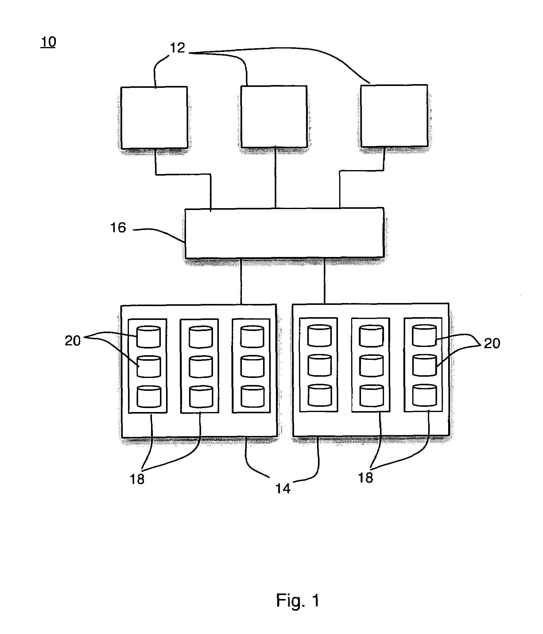
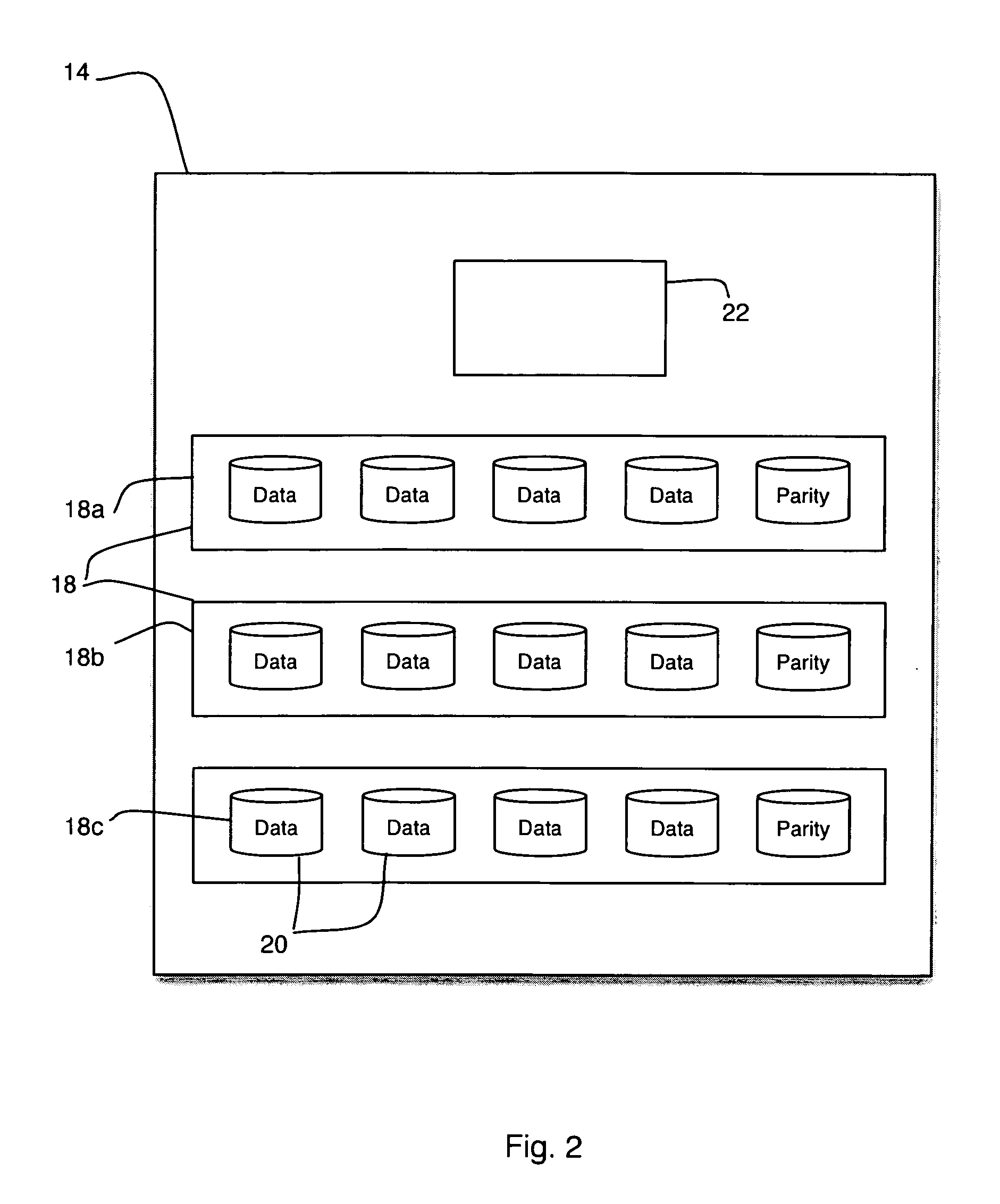
[0024]In FIG. 1 there is shown a functional block diagram of an exemplary storage system 10 in which the invention can be implemented. The storage system 10 includes one or more hosts 12 coupled to one or more storage arrays 14. The storage arrays 14 are shown coupled to each host 12 via a switch 16; however, the switch 16 may or may not be present. Each array 14 includes groups 18 of storage devices 20. There are many types of storage devices, including but not limited to disk drives, tape drives, optical disks, and solid state memory. For purposes of example, the storage devices employed in the embodiments herein described are disk drives, though the invention applies to all types of storage devices in all types of storage systems. For example, the invention can be employed in file-based networks or block-level networks as well as the storage area network shown in FIG. 1.

[0025]Sufficient redundancy is provided in each group 18 to ensure that data can continue to be read from and w...


PUM


Abstract

Redundancy in storage arrays is used to extend the life of disk drives and conserve power. In an exemplary storage array, a group of storage devices includes y storage devices. Data and redundant information is distributed across the y devices to provide m levels of redundancy. “Spun down devices” are provided by spinning down a set of one or more of up to m of the y storage devices. Meanwhile, data transfers to and from the group of storage devices continue to be serviced. After a predetermined time, the currently spun down disks can be spun up, and new spun down devices are provided by spinning down another set of one or more of m of the y storage devices. An array may include several groups of storage devices, each having its own value for y and m.

Description

FIELD OF THE INVENTION[0001]The present invention relates generally to the field of storage systems, and particularly to power management of disk drives in storage arrays.BACKGROUND OF THE INVENTION[0002]Today's enterprise data centers store ever-larger amounts of business critical data that must be immediately available and highly reliable. To meet reliability requirements for critical data, arrays of groups of disks are often employed. One type of array is known as a redundant array of independent disks (RAID array). Within a RAID array, data is distributed across groups of disks (“RAID groups”) in a manner consistent with the RAID level implemented, from full mirroring to parity protection.[0003]As applications demand larger amounts of storage, RAID arrays include many, even thousands, of disks. In order to control costs, inexpensive disk drives of the sort used in personal computers are often employed in RAID arrays. Such disks are not typically designed to work at a high duty c...

Claims


Application Information

Patent Timeline
Patent Type & Authority Patents(United States)
IPC IPC(8): G06F1/32
CPCG06F1/3268G06F3/0689G06F3/0625G06F1/3203G06F3/0634G06F1/3287G06F3/0616Y02B60/1246Y02B60/1278Y02B60/1282Y02D10/00
Inventor OFER, ADI
Owner EMC IP HLDG CO LLC
Why Eureka
Try Eureka