Two door electronic safe

a safe and electronic technology, applied in safes, special doors/window arrangements, instruments, etc., can solve the problems of slowing down the time to complete a transaction, affecting the purpose of electronic safes, and affecting the safety of electronic safes

Active Publication Date: 2009-04-14
ELLENBY TECH
View PDF15 Cites 20 Cited by
  • Summary
  • Abstract
  • Description
  • Claims
  • Application Information

AI Technical Summary

Benefits of technology

[0014]Another objective of the current invention is to provide an electronic drop safe with easy access and removal of serviceable components.
[0015]Yet, another objective of the current invention is to provide an electronic drop safe with easy access and quick removal of the cash canister.
[0017]Another objective of the current invention is to provide increased security against theft of the cash canister by eliminating the bill entry holes from the cash canister access door.

Problems solved by technology

A significant disadvantage of these safes is that in the event of a failure or bill jam, the electronic safe is out of service and cashiers either have to use another safe thus slowing down the time to complete a transaction or worse, a cashier may be forced to leave excess cash in the cash drawer.
Of course, such a nonsecure buildup of cash, defeats the purpose of the electronic safe.
Adding to the problem is that unless the facility has the technical expertise to service the safe, an outside service provider has to be contacted to repair or replace the defective component.
In many cases, the problem is centered on the bill acceptor as it has the only moving parts and suffers from wear.
The high volume of bills many of these electronic safes receive will result in expected wear and tear issues, and preventive maintenance may typically be expected in six months to a year.
This present arrangement has several problems.
Second, in many cases, just opening the door signals the electronic controller of the safe that a “collection” is being made.
Such unscheduled collections result in cash sitting in the manager's office, or being put in another safe on the premises.
If an armored carrier service is used and is responsible for collecting and counting all the cash, that service may have to be called to make an unscheduled and expensive pickup.
There are also other disadvantages of the current typical approach.
Equipment going out of service impacts their business.
The current service issues as described above makes such rapid response difficult or even impossible.
If the manager or collection service must also be present for a service person to have access to the safe, the available time for service is usually limited to the working or available hours of the manager or collection service.
Unfortunately, this period is also when these retail outlets are busiest.
Such daytime access to the electronic safes by service persons disrupts normal business operation.
In addition to forcing access to the currency and the resulting complications as discussed above, most of the electronic safes manufactured today require tools to disassemble the bill acceptor from the safe and therefore it takes some time to complete a service call at the safe.
As discussed above, the security of current electronic safes is limited by the requirement that the bills are fed through an opening in the safe.
Even if not successful, destroying the bill acceptor in an attempt to gain access results in a costly repair.
The bill acceptor is the most costly component in the electronic safe.
Peripheral damage to the safe box and other components adds to the cost of the repair.

Method used


Image

  • Two door electronic safe
  • Two door electronic safe
  • Two door electronic safe

Examples


Embodiment Construction

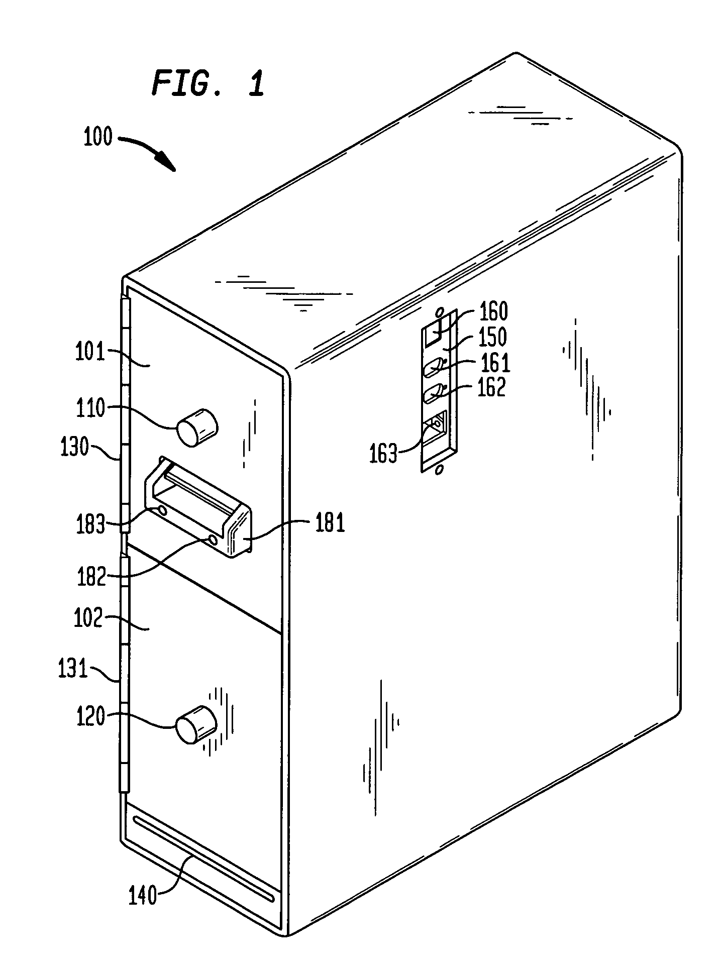
[0025]Referring to FIG. 1, an electronic drop safe 100 in accordance with the present invention is shown in a perspective view. The safe 100 is typically made from ⅛″ to ¼″ steel with the doors constructed from ¼″ to ½″ steel. The size of the safe is designed so that it will conveniently fit under a counter near a cash register or POS terminal, although any convenient location is suitable. In a presently preferred embodiment, the safe height will be less than 20″, its width about 6″, and its depth about 15″.

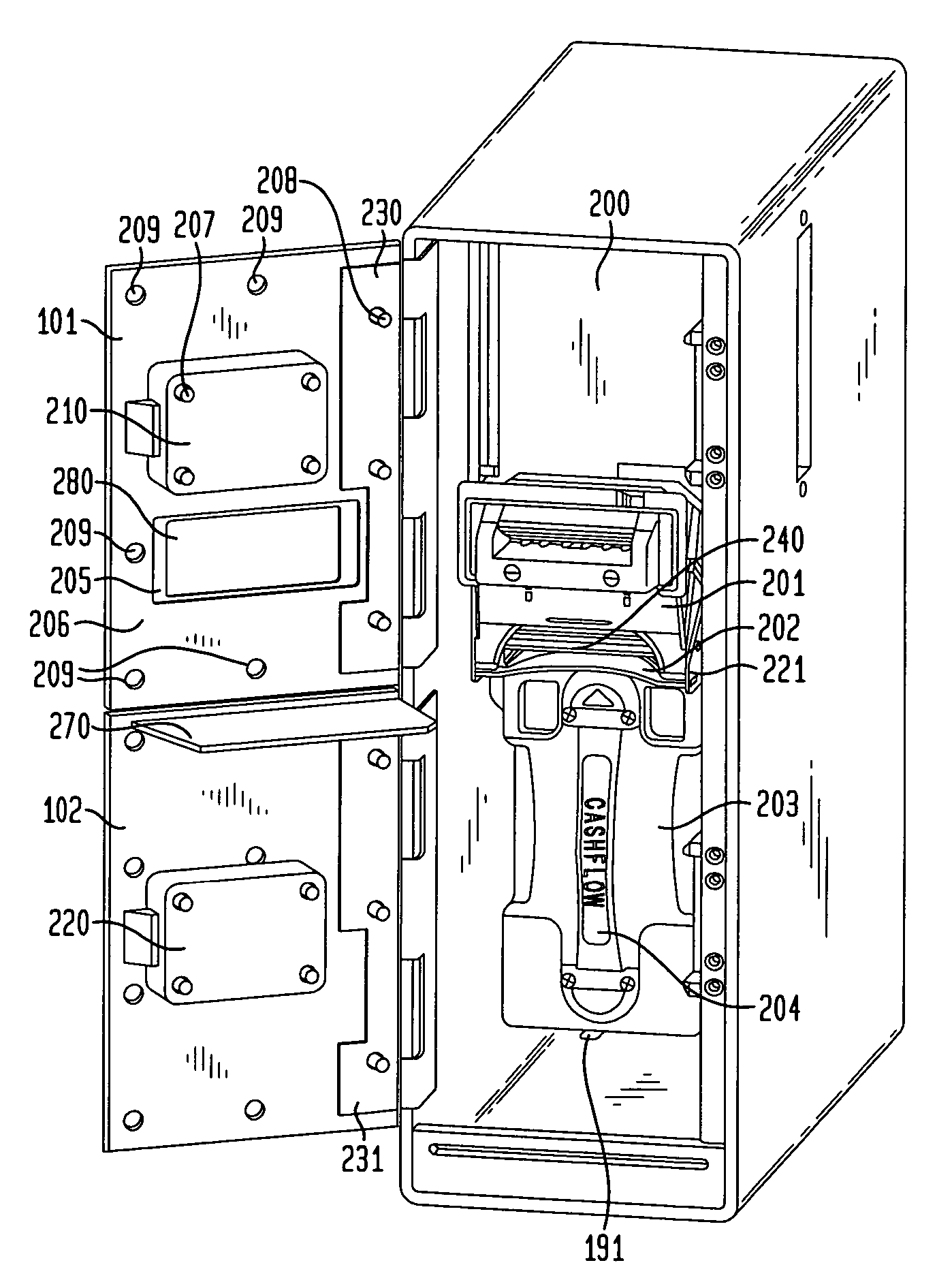
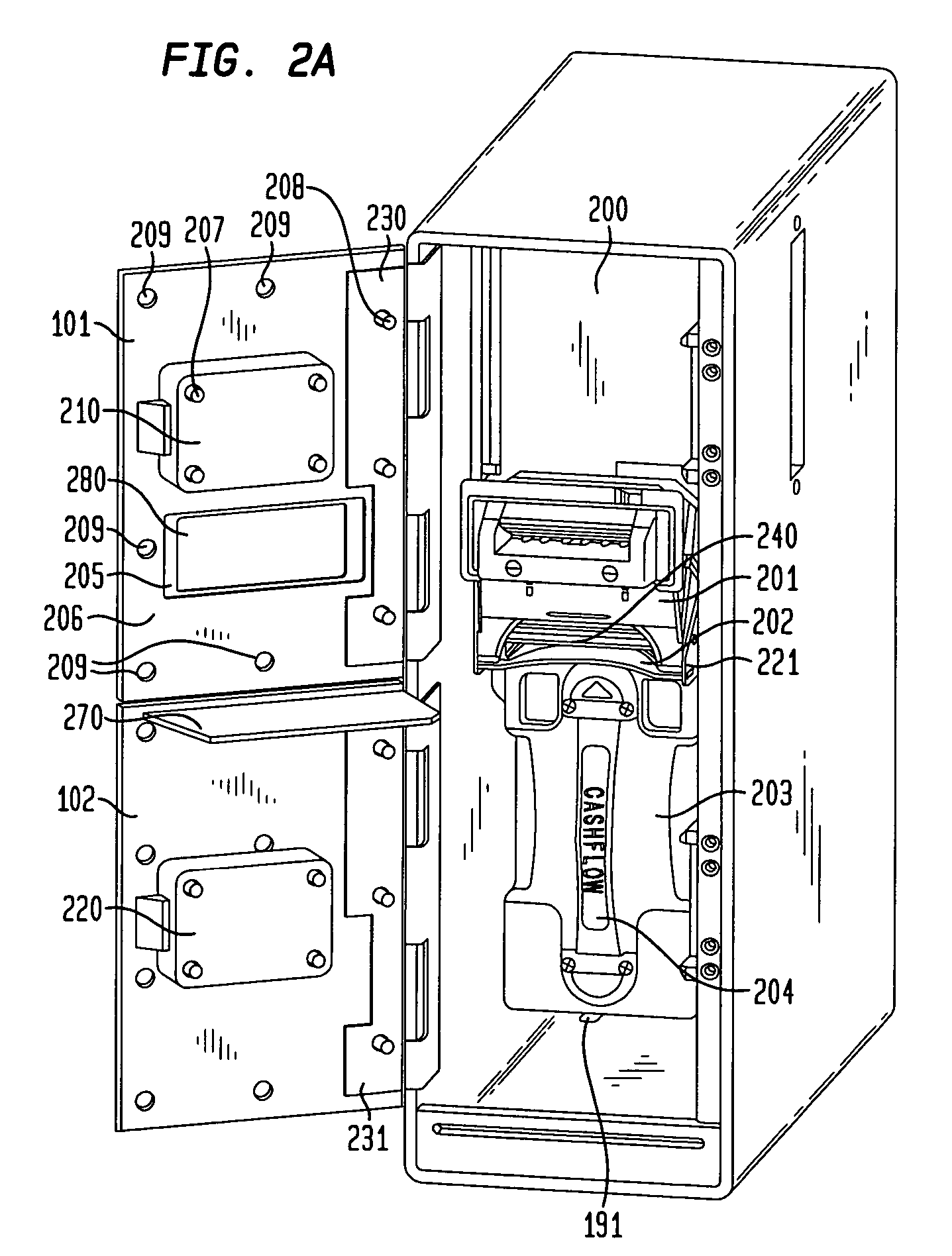
[0026]The electronic drop safe 100 is designed to be bolted in place with the bolts extending up into the safe from the flooring or base cabinetry. For this purpose, the safe base has multiple bolt clearance slots 190 and 191 best seen in FIGS. 2A and 2B. It will be recognized that other methods of mounting the safe can be used, and the particular approach to mounting does not serve as a limitation of this patent.

[0027]The electronic drop safe 100 is equipped with at least two do...


PUM


Abstract

A two door electronic safe is described wherein a bill acceptor, as well as other electronic control circuitry, and a banknote canister are partitioned in first and second compartments with access by first and second access doors, respectively, so that a service call can be made to service the bill acceptor or other electronics without having to allow access to the banknote canister thereby facilitating service calls and allowing the separation of the service call function from the cash collection function.

Description

[0001]The present application claims the benefit of U.S. Application Ser. No. 60 / 496,515 filed Aug. 20, 2003 which is incorporated by reference herein in its entirety.FIELD OF THE INVENTION[0002]The present invention relates generally to advantageous aspects of an improved electronic drop safe. More particularly, the present invention relates to such a safe with separate access to a serviceable electronics area and a stored currency area of the safe.BACKGROUND OF THE INVENTION[0003]The use of electronic drop safes in applications in which cash is a significant payment media results in increased security for cashiers and store managers, as well as, reducing the risk of robbery or theft of the cash stored in such safes. There are a number of products on the market, such as the Ellenby Technologies, Inc. CashTrak Electronic Safe™. Although this class of safe is not considered a security safe since there are openings in the unit to allow access to currency or bills, it is effective in s...

Claims


Application Information

Patent Timeline
Patent Type & Authority Patents(United States)
IPC IPC(8): G07F9/10E05G1/00E05G1/024E05G1/026G07D11/00G07F7/04
CPCG07D11/0006G07F7/04G07D11/12
Inventor DOBBINS, BOB M.
Owner ELLENBY TECH
Why Eureka
Try Eureka