Rotary cutter head

a rotary cutter and cutter head technology, applied in the direction of shaping cutters, flat surface machines, manufacturing tools, etc., can solve the problems of dislodging the cutter blade slightly, the pins and the gibs used in the cutter head easily falling out of the recess,

Active Publication Date: 2009-04-14
GREAT LAKES CUSTOM TOOL MFG
View PDF14 Cites 8 Cited by
  • Summary
  • Abstract
  • Description
  • Claims
  • Application Information

AI Technical Summary

Benefits of technology

[0011]The general aim of the present invention is prevent the cutting blade from slipping out of position in a radial direction due to centrifugal forces generated from high speed rotation of the cutter head during operation.
[0012]In accordance with this aim, an aspect of the present invention is directed towards an improved rotary cutter head which includes a clamp that positively locks one or more cutting blades in a radial direction. This positive radial clamping prevents the cutting blade from slipping slightly in a radially outward direction in response to centrifugal force generated by high rotational speeds of the cutter head. According to this aspect, the rotary cutter head includes a rotary cutter head body, at least one clamp which is moveable relative to the body to open and close a clamping recess and one or more cutting blades. The cutting blade has a slot which receives a tab provided by the corresponding clamp. When the clamp member is clamped down, the tab on the clamp member engages the inner side wall of the cutting blade. This causes the base end of the cutting blade to engage the bottom of the recess formed in the rotary cutter head body to positively lock the cutting blade in the radial direction. This prevents the cutting blade from inadvertently slipping radially outwardly during subsequent high-speed rotation of the cutter head.
[0013]One aspect of the present invention is directed toward a cutting blade which is configured to prevent the blade from migrating slightly out of position in the radial direction due to centrifugal force. The cutting blade is intended for use with a rotary cutter head as described above. This cutter head includes a resilient clamping arm that is adapted to clamp the cutting blade in a recess defined in the rotary cutter head. To accomplish this aspect, the cutting blade includes a specially configured slot on the leading face of the cutting blade which is intended to mate with a corresponding tab formed in the clamping arm on the rotary cutter head. The location and size of the slot is such that it provides means for ensuring that the cutting blade clamps in a radially inward direction when installed on the cutter head body. Specifically, the cutting blade slot is sized and positioned to ensure that the base end of the cutter blade and the bottom of the cutter head recess are positively engaged against each other when the cutter blade is clamped into the cutter head. This prevents the cutting blade from wandering radially outward during high speed rotation.

Problems solved by technology

Moreover, the pins and the gib used in this cutter head easily fall out of the recess when the fasteners are inadvertently loosened too far.
However, it has been realized that high speed rotation of the cutter head can generate large centrifugal forces which can dislodged the cutter blade slightly.

Method used


Image

  • Rotary cutter head
  • Rotary cutter head
  • Rotary cutter head

Examples


Embodiment Construction

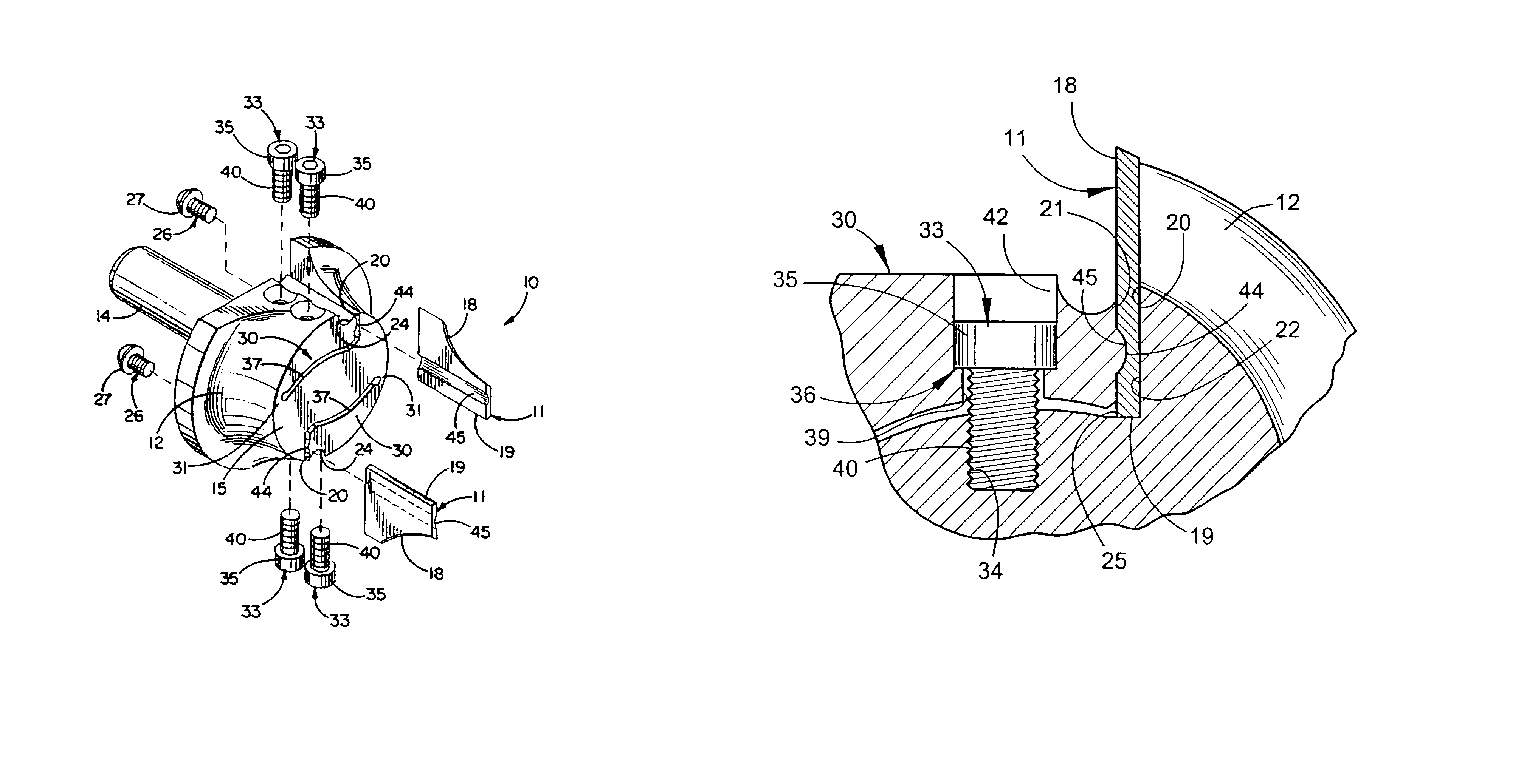
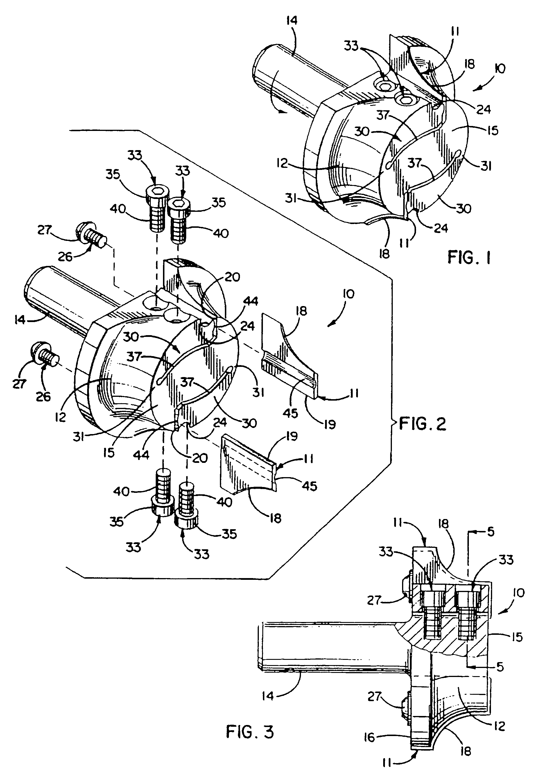
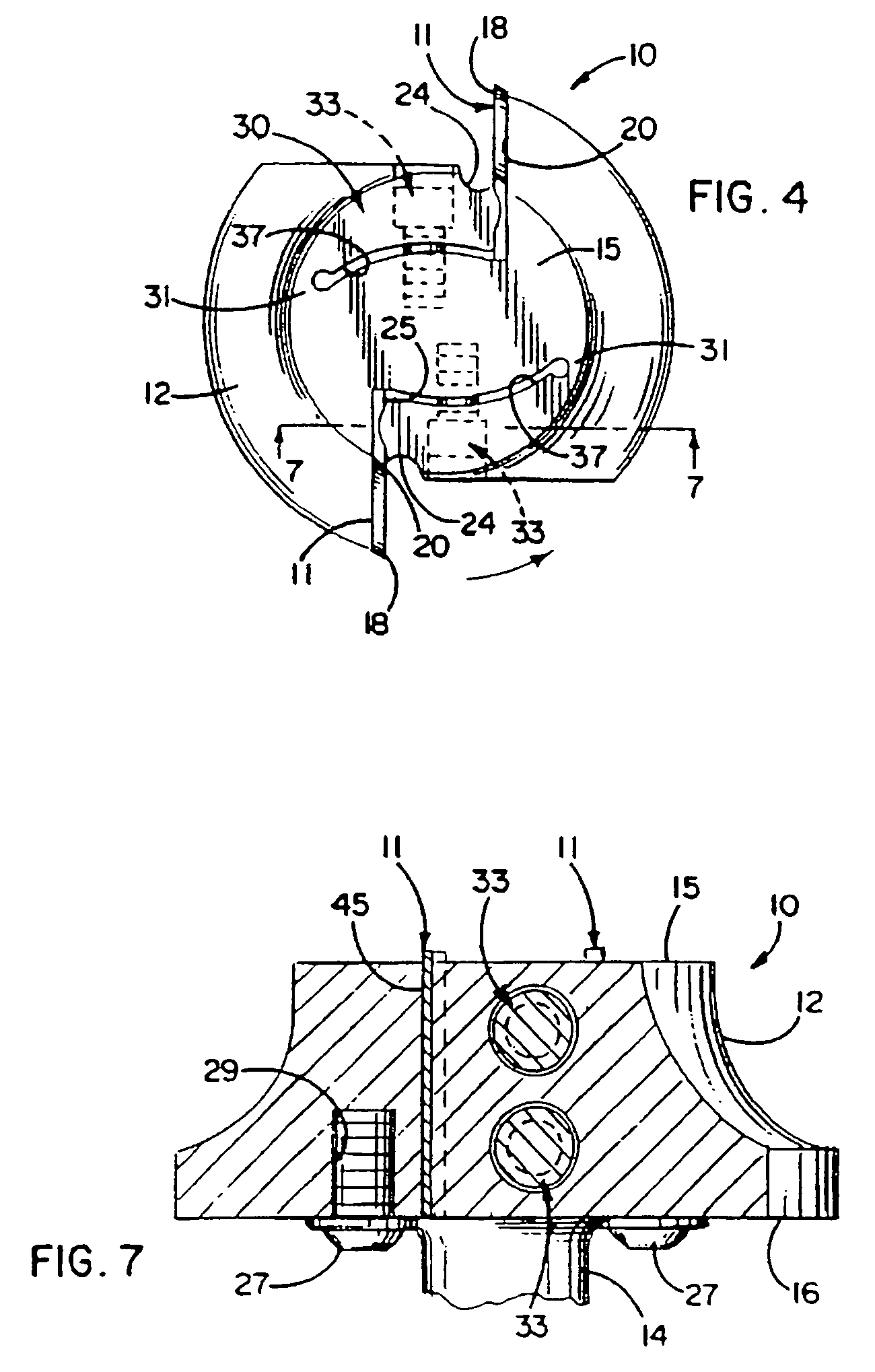
[0024]For purposes of illustration, the present invention is shown in the drawings as embodied in a cutter head 10 (FIG. 1) adapted to be installed in a rotary power tool such as a router (not shown) and adapted to releasably hold replaceable cutting blades 11 for shaping the edge portion of, for example, a wood or plastic workpiece (not shown).

[0025]The cutter head 10 includes a body 12 and a shank 14. The body is formed with front and back surfaces 15 and 16 (FIG. 3), respectively, and with a generally radially facing outer periphery which defines a substantially circular cross-section. The shank extends rearwardly from the center of the back surface and is sized to be received into a chuck or a collet of the rotary power tool such that the shank portion establishes the axis of rotation for the cutter head. Alternately, the body may be formed with a centrally located hole suitable for mounting to an arbor or a spindle of the power tool. The cutter head shown is adapted to be rotat...


PUM

PropertyMeasurementUnit
sizeaaaaaaaaaa
dimensionaaaaaaaaaa
widthaaaaaaaaaa

Abstract

A rotary cutter head includes a rotary body, resilient clamping arm, and at least one cutting blade. The clamping arm clamps the cutting blade radially inwardly first rather than in a circumferential direction in order to positively lock the cutting blade radially, and thereby prevent the cutting blade from migrating out of position slightly during high speed rotation of the cutter head.

Description

CROSS REFERENCE TO RELATED APPLICATIONS[0001]This patent application claims the benefit of U.S. Provisional Patent Application No. 60 / 667,810, filed Apr. 1, 2005.FIELD OF THE INVENTION[0002]This invention pertains to an improvement for a cutting tool for use in a rotary power tool. More particularly, the invention relates to rotary cutter heads and cutting blades for use therewith.BACKGROUND OF THE INVENTION[0003]A rotary cutter head for releasably holding cutting blades is formed with cutting edges which extend radially outwardly of and generally axially along the outer periphery of the cutter head. Cutter heads of this general type are typically used in power machines such as routers, moulders, shapers or tenoners and are typically used to chamfer, round, or otherwise shape an edge portion of a workpiece of either non-ferrous metals, plastics, woods, etc.[0004]In general, a cutter head of this type is formed with at least one recess for receiving a cutting blade. The recess extend...

Claims


Application Information

Patent Timeline
Patent Type & Authority Patents(United States)
IPC IPC(8): B23D13/00B23C5/22
CPCB27G13/10B27G13/12Y10T407/225Y10T407/194Y10T407/1906
Inventor MARTIN, RUSS L.
Owner GREAT LAKES CUSTOM TOOL MFG
Why Eureka
Try Eureka