
Connection device for an electrical machine

a technology for connecting devices and electrical machines, applied in the direction of coupling device connections, coupling device details, association with control/drive circuits, etc., can solve the problems of increasing installation space, high degree of complexity in terms of variance or adapter parts, and increasing costs. , to achieve the effect of reducing logistical complexity

Active Publication Date: 2009-04-14
SIEMENS AG
View PDF12 Cites 5 Cited by
  • Summary
  • Abstract
  • Description
  • Claims
  • Application Information

AI Technical Summary

Benefits of technology

[0009]The object of the present invention consists in proposing a connection device which reduces the logistical complexity and the fitting complexity in comparison with known systems.
[0013]In accordance with one preferred embodiment of the connection device according to the invention, connection elements for the external contacts can be snapped into the base body. This makes it possible for the external contacts to be connected in a very simple manner.
[0015]The contacts of the electrical machine are advantageously flat plugs or similar contacts which can be snapped into the base body or connection elements located therein. As a result, the machine-side contacts can easily be connected to the base body before it is fitted into the terminal box socket of the electrical machine.
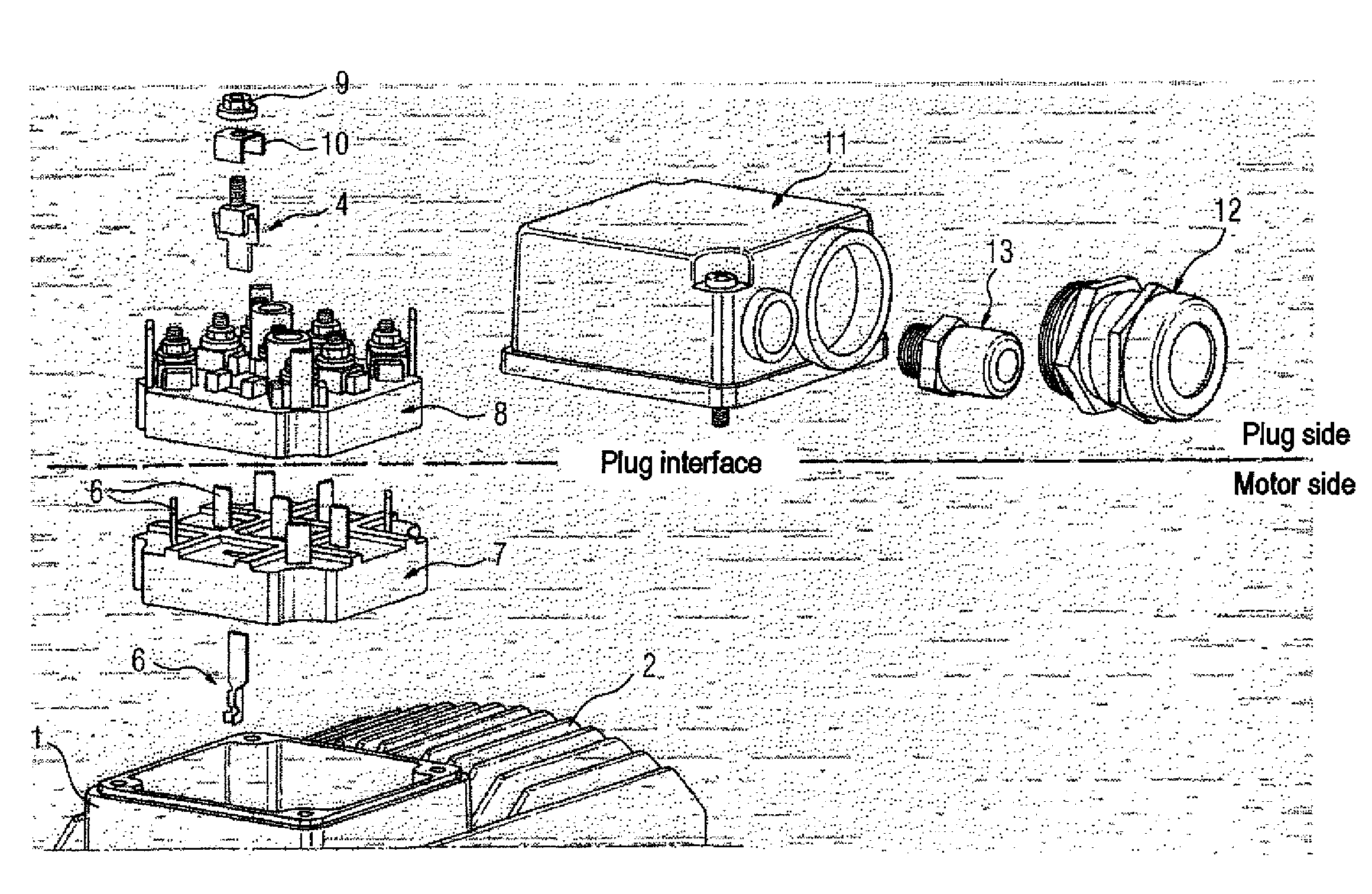
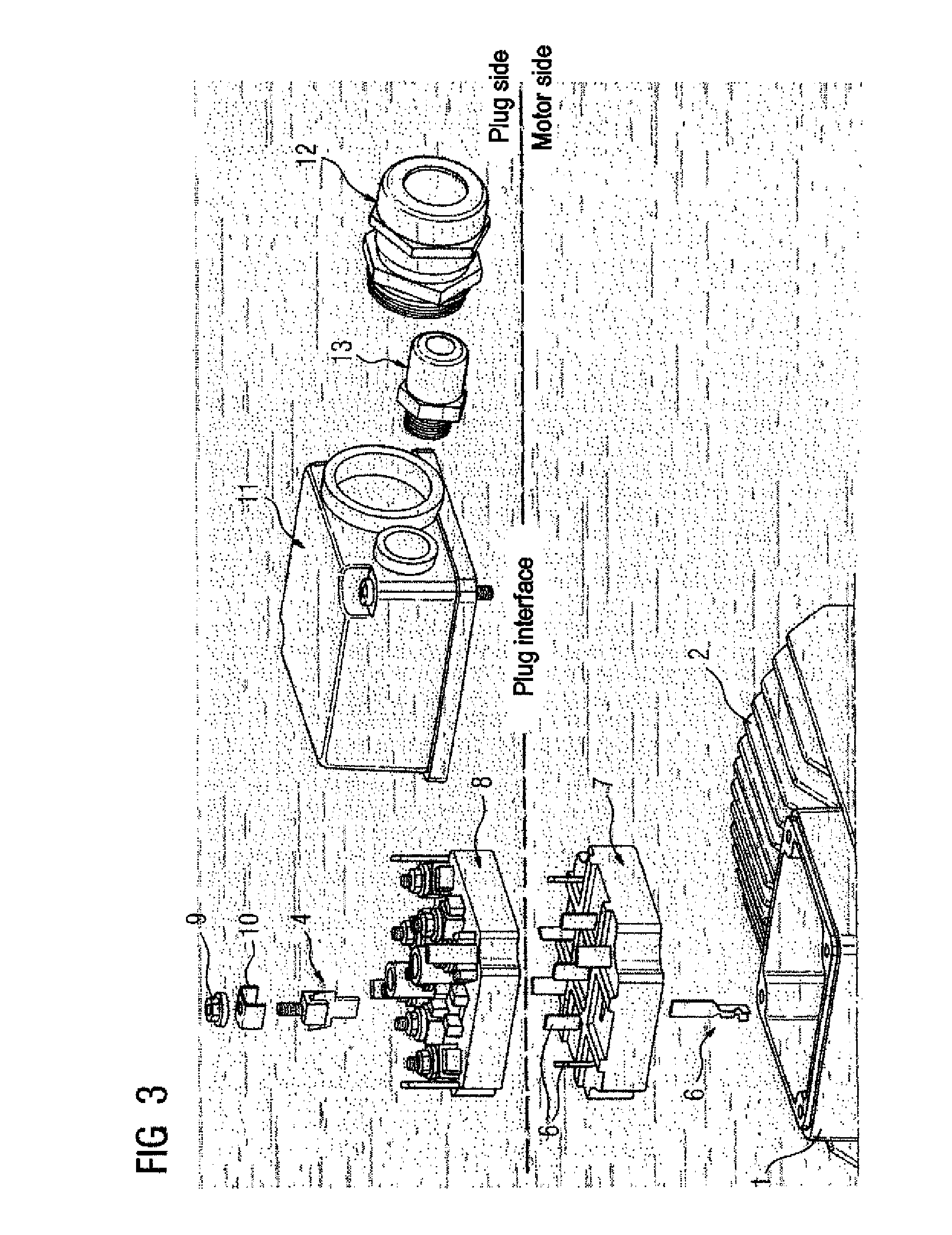
[0016]In accordance with one advantageous development of the connection device according to the invention, a plug housing or terminal box housing having a first opening for power lines and a separate, second opening for control lines is fitted onto the terminal box socket of an electrical machine such that it can be removed. In this manner, interference signals in the control lines, which may be brought about by the power lines, can largely be avoided.

Problems solved by technology

In order to change the type of connection, a high degree of complexity in terms of variance or adapter parts is generally required.
This often results in severely increased costs and in many cases requires more installation space, in addition.
In many uses, the ideal type of connection can therefore not be used for technical and economic reasons.
Furthermore, the large number of possibilities for external connections results in a high degree of external variance.
This not only increases the logistical complexity, but also the fitting complexity for the connection systems.

Method used


Image

  • Connection device for an electrical machine
  • Connection device for an electrical machine
  • Connection device for an electrical machine

Examples


Embodiment Construction

[0022]The exemplary embodiments described in more detail below represent preferred embodiments of the present invention.

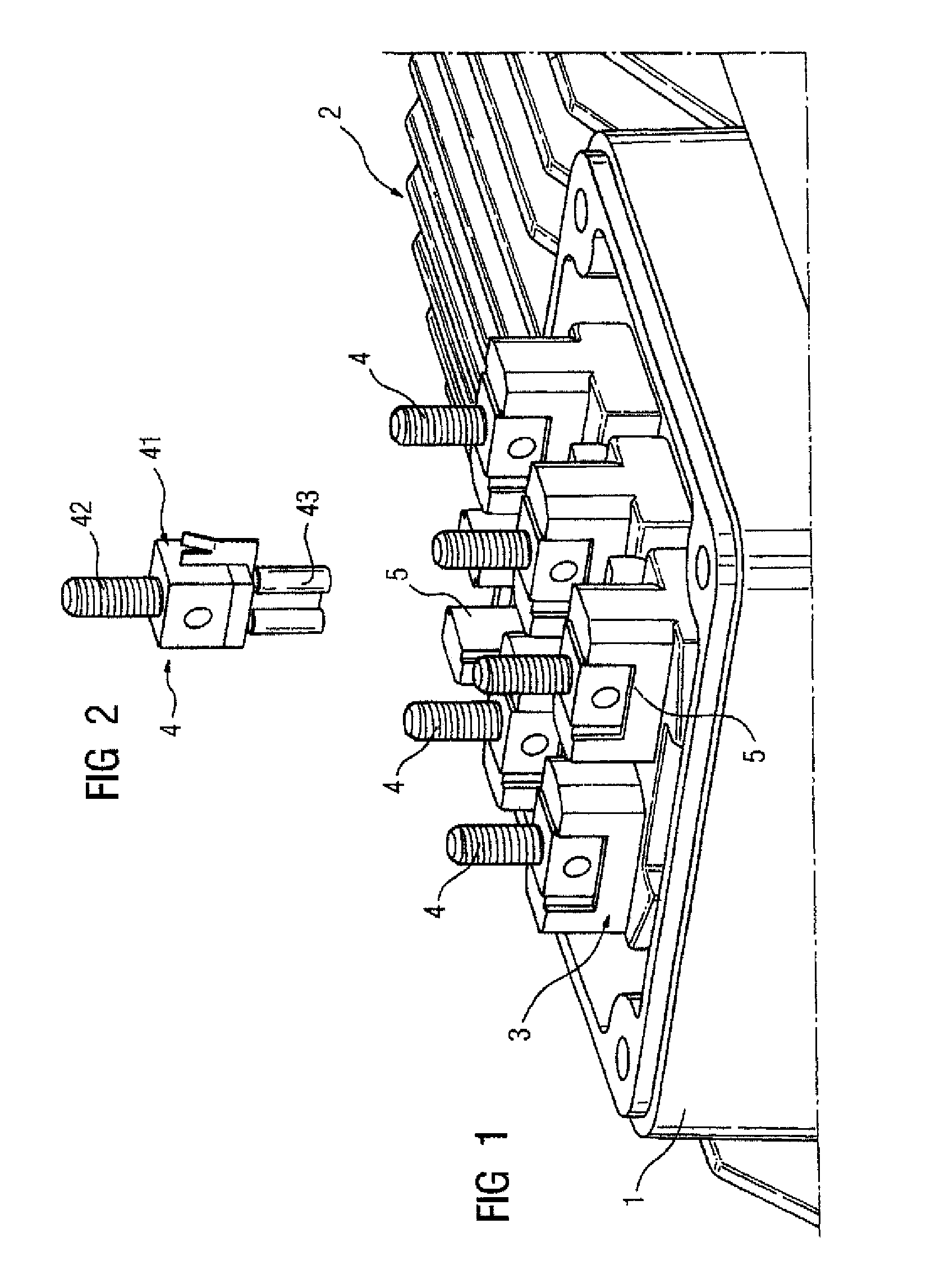
[0023]The connection system illustrated in FIG. 1 represents, in terms of the connection principle, a preliminary stage of the present invention and is installed in a terminal box socket 1 of a motor housing 2. It comprises a terminal board base body 3, into which connection elements 4 are plugged or can be plugged. For this purpose, the terminal board base body 3 has corresponding female connectors 5.

[0024]FIG. 2 illustrates the connection element 4 in the unplugged state. In the present case, it has a cuboid central section 41, at which a threaded bolt 42 is located. A flat plug-in sleeve 43 is fixed into that side of the central section 41 which is opposite the threaded bolt 42.

[0025]In the present, typical case, six connections are provided for the motor illustrated. The terminal board base body 3 may also have any other desired number of connection possibiliti...


PUM


Abstract

The aim of the invention is to reduce the logistical and assembly expenses during the connection of electrical machines. To this end, a connection device is provided with a base body (7) that can be mounted in a terminal box socket (1) of the electrical machine. A plurality of contacts (6) of the electrical machine can be plugged or clipped into said base body (7). Outer contacts can be connected to the base body (7) by means of connection elements (4). Preferably, the connection elements (4) are collected together by a plug housing base body (8) in such a way that a plug-in system is provided by means of the socket base body (7).

Description

BACKGROUND OF THE INVENTION[0001]The present invention relates to a connection device for an electrical machine and in particular for electric motors.[0002]For different types of use of electric motors there are also different requirements placed on the configuration of the electrical connection system. Each of the various connection systems requires in each case completely different connection components. In order to change the type of connection, a high degree of complexity in terms of variance or adapter parts is generally required. This often results in severely increased costs and in many cases requires more installation space, in addition. In many uses, the ideal type of connection can therefore not be used for technical and economic reasons.[0003]Nowadays, motors are typically connected, for example, via terminal boards, in which the motor-side connection contacts and the external connection contacts are in each case screwed on. In accordance with another connection variant, ...

Claims


Application Information

Patent Timeline
IPC IPC(8): H01R9/22
CPCH01R29/00H02K5/225H02K5/10H02K11/0073H01R4/30H01R13/115H01R13/428H02K11/33
Inventor HANDWERKER, MICHAEL
Owner SIEMENS AG
Learn More