Airway bypass site selection and treatment planning

a site selection and treatment planning technology, applied in the field of airway bypass site selection and treatment planning, can solve the problems of limiting the areas of the airway that are treatable, unable to access the target airway surface, and creating an extra-anatomic passage too close to the blood vessel is obviously not desired

Active Publication Date: 2009-04-14
BRONCUS MEDICAL
View PDF68 Cites 148 Cited by
  • Summary
  • Abstract
  • Description
  • Claims
  • Application Information

AI Technical Summary

Benefits of technology

[0020]Previous studies indicate that successful site selection for creation of an extra-anatomic passage includes the ability to gain access to the target airway surface, transbronchial access to trapped gases within the lungs or at least transbronchial access to collateral ventilation paths in the lung, as well as creation of the extra-anatomic passage in an area that is anatomically safe.

Problems solved by technology

For example, the ability to access the target airway surface may be difficult or impossible if the surgical system is unable to navigate to the site.
Since the surgical system used to perform the procedure may include any number of components, the component limitations may limit the areas of the airway that are treatable.
For example, creation of an extra-anatomic passage too close to a blood vessel is obviously not desired.
Furthermore, creation of an extra-anatomic passage outside of the parenchymal border of the lung may result in a treatment without benefit or at the worst case, a pneumomediastinum (i.e., free air in the mediastinum that may give rise to pneumothorax or pneumopericardium and compromise the lungs or heart).
Alternatively, creating the passage too close to the outer periphery of the lung may result in a pneumothorax.

Method used


Image

  • Airway bypass site selection and treatment planning
  • Airway bypass site selection and treatment planning
  • Airway bypass site selection and treatment planning

Examples


example 1

[0085]1. Identify the treatable regions of the 18 segmental segments in the 5 lobes of the lung for:

[0086]1.1 Airway diameter distance from mouth, articulation angles, and intraparenchymal margin to determine bronchoscopic access and treatable surfaces;

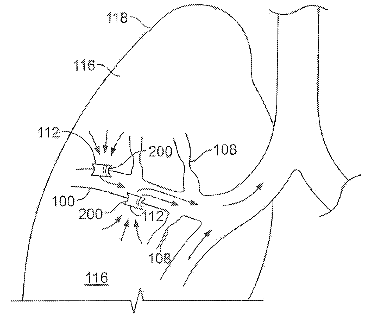
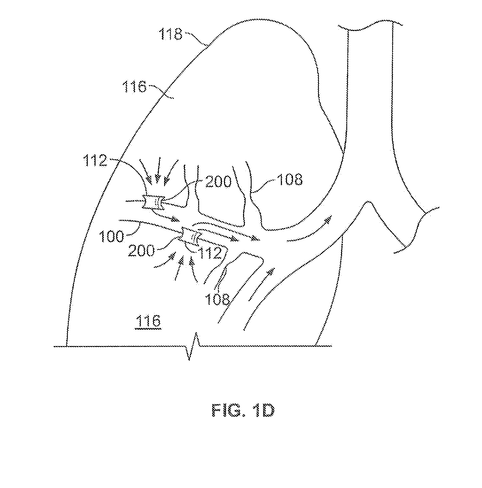
[0087]2. Once the treatable regions are identified, evaluate the vessel free locations by:

[0088]2.1 Tracking the branches of the pulmonary arteries and veins from the 2 arterial and 2 venous vessels entering and exiting the lung, then

[0089]2.2 Identifying locations within the treatable regions with sufficient distance from the pulmonary branches

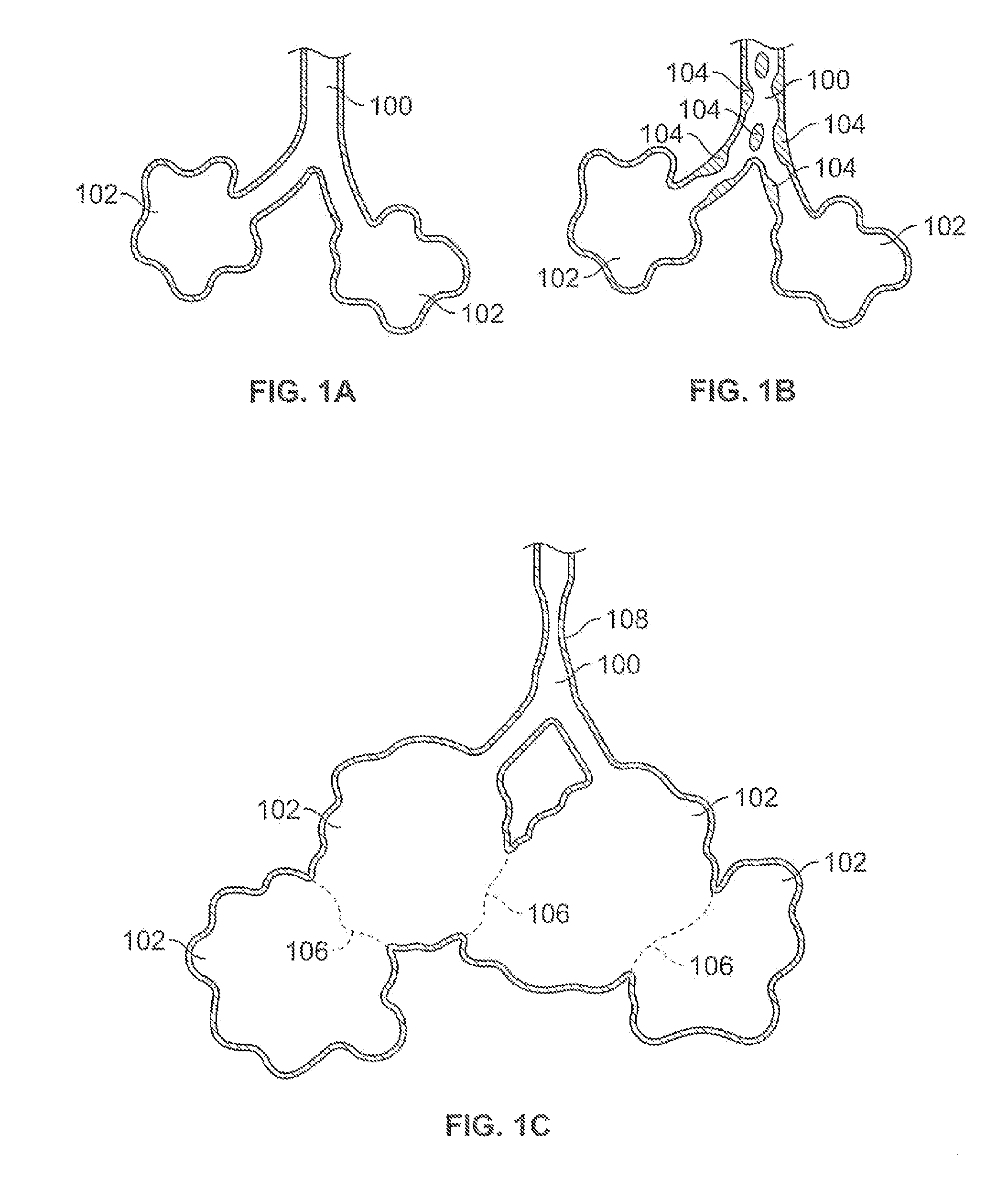
[0090]3. Once the vessel free locations within the treatable regions are identified, evaluate the access to trapped gas by:

[0091]3.1. Determining the accessible parenchymal tissue density within local and regional volumes

[0092]3.2. Ranking the treatment locations by local and regional tissue density

[0093]4. Creating a site road may to indicate to the bronchoscopist the preferred treatment locat...

example 2

[0094]1. Identify the regions of trapped gas, by:

[0095]1.1. Determining the local and regional parenchymal tissue densities throughout the lung

[0096]1.2. Rank ordering the regions

[0097]2. Evaluating transbronchial access paths to the trapped gas or collaterally ventilated regions by;

[0098]2.1. Identifying the segmental airways communicating with the regions, and

[0099]2.2. Determining bronchoscopic access and the treatable regions within these segments.

[0100]3. Identifying the blood vessel free locations, by

[0101]3.1. Tracking the branches of the pulmonary arteries and veins from the 2 arterial and 2 venous vessels entering and exiting the lung, then

[0102]3.2. Identifying locations within the treatable regions with sufficient distance from the pulmonary branches

[0103]4. Creating a site road map to indicate to the bronchoscopist the preferred treatment locations.

[0104]The invention herein it described by examples and a desired way of practicing the invention is described. However, the...


PUM


Abstract

The invention relates to systems and methods for site selection and placement of extra-anatomic passages altering gaseous flow in a diseased lung.

Description

FIELD OF THE INVENTION[0001]The invention relates to methods and systems to select sites within the lungs that allow expired air to pass out of the lung tissue to facilitate both the exchange of oxygen ultimately into the blood and / or to decompress hyper-inflated lungs.BACKGROUND OF THE INVENTION[0002]The American Lung Association (ALA) estimates that nearly 16 million Americans suffer from chronic obstructive pulmonary disease (COPD) which includes diseases such a chronic bronchitis, emphysema, and some types of asthma. The ALA estimated that COPD was the fourth-ranking cause of death in the U.S. The ALA estimates that about 14 million and 2 million Americans suffer from emphysema and chronic bronchitis respectively.[0003]Those inflicted with COPD face disabilities due to the limited pulmonary functions. Usually, individuals afflicted by COPD also face loss in muscle strength and an inability to perform common daily activities. Often those patients desiring treatment for COPD seek ...

Claims


Application Information

Patent Timeline
Patent Type & Authority Patents(United States)
IPC IPC(8): A61B5/08
CPCA61B5/02007A61B6/00A61B1/2676A61B5/08A61B5/1075A61B6/481A61B8/12
Inventor WIBOWO, HENKYROSCHAK, EDMUND J.KEAST, THOMAS M.COLE, CARY
Owner BRONCUS MEDICAL
Why Eureka
Try Eureka