Surgical tool system including plural powered handpieces and a console to which the handpieces are simultaneously attached, the console able to energize each handpiece based on data stored in a memory integral with each handpiece

a technology of powered handpieces and consoles, applied in the field of powered surgical tools, can solve the problems of time also needed, high cost of solution, and clutter in the operating suite, and achieve the effect of convenient tool us

Inactive Publication Date: 2009-04-14
STRYKER CORP
View PDF31 Cites 164 Cited by
  • Summary
  • Abstract
  • Description
  • Claims
  • Application Information

AI Technical Summary

Benefits of technology

[0016]This invention relates to an improved integrated system for powered surgical tools that facilitates the use of tools having different power and control signal requirements and that allows the individual tools to be used with different combinations of accessory units.

Problems solved by technology

As can readily be understood, this solution is expensive in that it requires hospitals and other surgical facilities to keep a number of different consoles available, in the event a specific set of tools are required to perform a given surgical procedure.
Having to provide these different consoles contributes to clutter in the operating suite.
While these consoles have performed satisfactorily they are not without their own disadvantages.
Moreover, given the inevitable human error factor, time also needs to be spent to ensure that once configured for a new tool, a console is, in fact, properly configured.
While these powered tool systems have proved useful, they are of limited value in that any significant information about the tool, such as an indication of the maximum power that can be applied thereto, or the maximum speed at which its motor can be driven must be contained within the complementary console.
It can be quite costly to provide a number of different tools, each with its own set of accessory features, in order to make appropriate accommodation for individual personal preferences and surgical requirements.
The need to provide these additional control consoles further contributes to both the cost of properly equipping an operating suite and the clutter within the suite.
These holders still have the potential of interfering with the grasp of the tools to which they are attached.
Still another disadvantage of this type of tool assemblies is that their light-and-water units have complementary control buttons that are depressed in order to control the actuation of these units and their rates of operation.
The presentation of these buttons, when they are not needed thus presents surgical personnel with extraneous information that may detract their attention from the matters and instrument controls on which they should be concentrating.
Still other new tools do not even include traditional electrically powered motors.
Having to provide this additional equipment has further contributed to the cost and complexity of equipping a surgical suite.

Method used


Image

  • Surgical tool system including plural powered handpieces and a console to which the handpieces are simultaneously attached, the console able to energize each handpiece based on data stored in a memory integral with each handpiece
  • Surgical tool system including plural powered handpieces and a console to which the handpieces are simultaneously attached, the console able to energize each handpiece based on data stored in a memory integral with each handpiece
  • Surgical tool system including plural powered handpieces and a console to which the handpieces are simultaneously attached, the console able to energize each handpiece based on data stored in a memory integral with each handpiece

Examples


Embodiment Construction

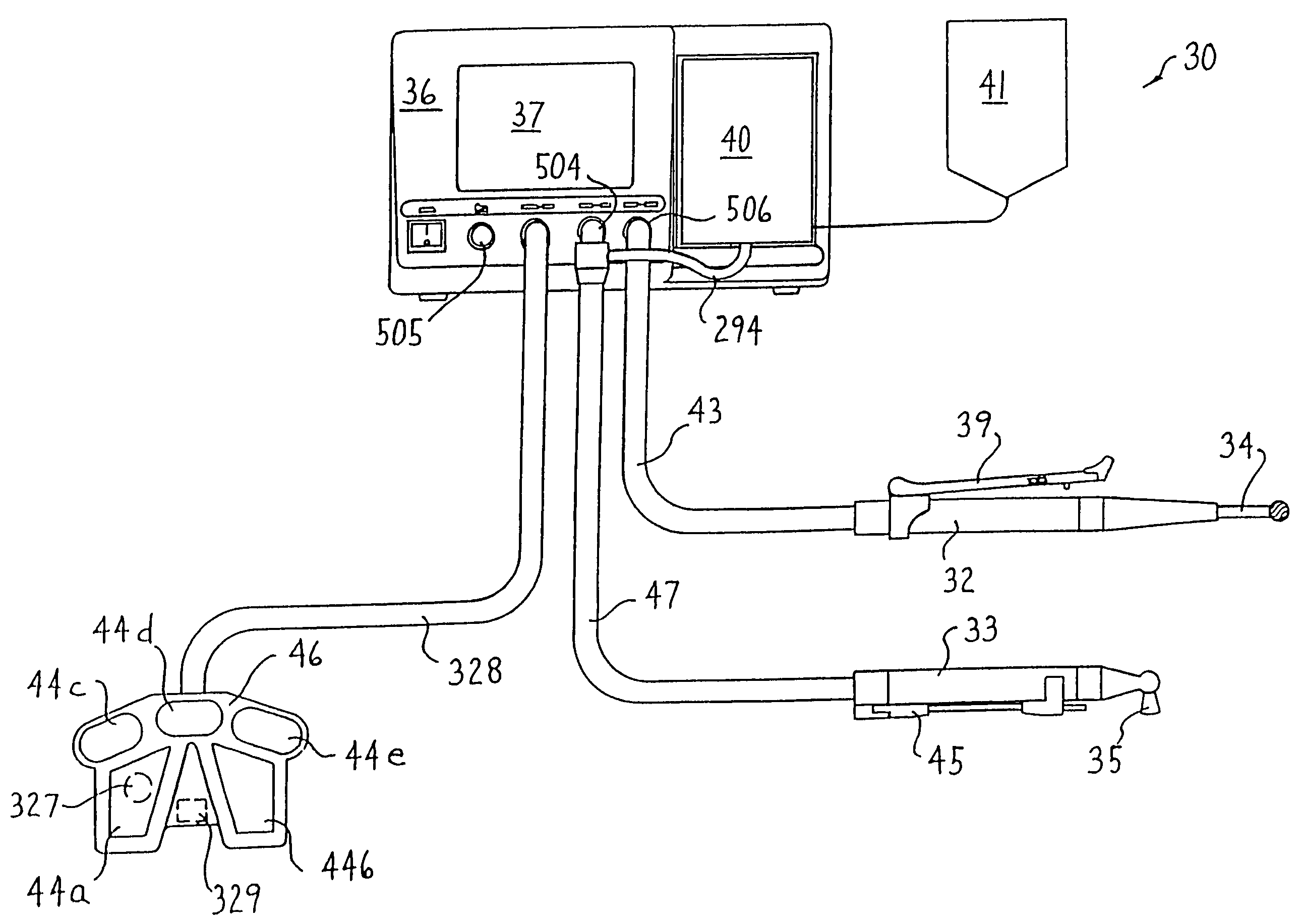
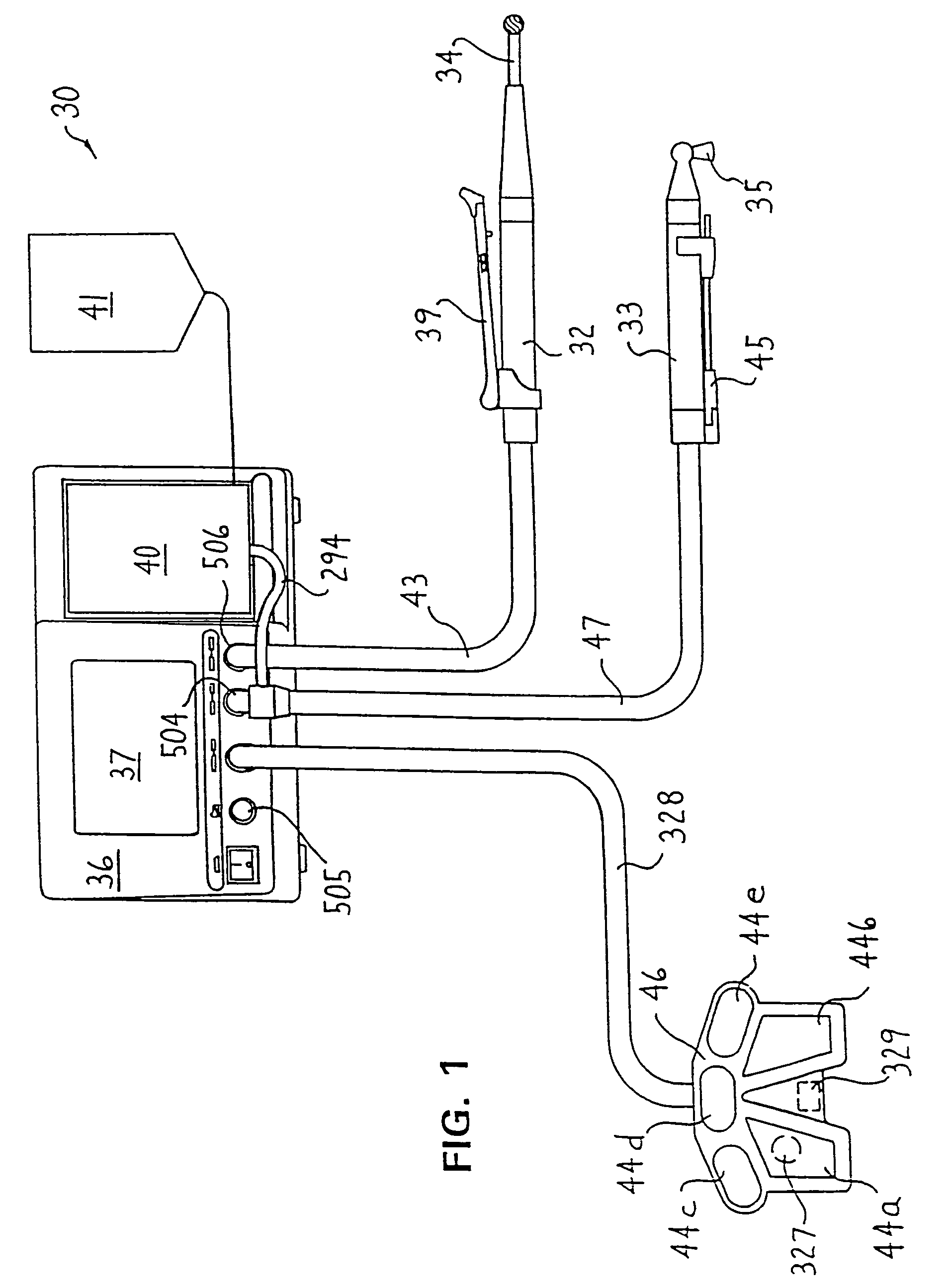
[0053]FIG. 1 depicts the basic components of the integrated surgical tool system 30 of this invention. System 30 includes two surgical tools, referred to as handpieces 32 and 33. Each handpiece 32 and 33 contains an electrically driven motor. A cutting attachment, here a burr 34, is coupled to handpiece 32 so as to rotate with the actuation of the motor. A saw 35 serves as the cutting attachment for handpiece 33. The power for energizing the motor within the handpiece 32 or 33 comes from a control console 36. The control console 36 selectively energizes the handpieces 32 and 33 in response to user-entered commands and further monitors the operation of the handpieces. A touch screen display 37 integral with control console 36 serves as the interface through which information about the handpieces 32 and 33 is presented to surgical personnel and through which some commands used to control the handpieces are supplied to the control console.

[0054]The on / off operation and speed of handpie...


PUM


Abstract

A surgical tool system (30) with a powered surgical handpiece (32). A removable handswitch (39) is attached to the handpiece. The handswitch includes a slip ring (192) that removably holds the handswitch to the handpiece. A lever arm (212) is pivotally attached to the slip ring. A magnet (190) is fitted in the lever arm. The angle of the lever arm is set by the surgeon to indicate the on / off state and operating speed of the handpiece. Internal to the handpiece is a sensor (94) that generates a signal based on the relative proximity of the magnet. The sensor signal is thus employed as the control signal for regulating the operation of the handpiece. Thus a surgeon can selectively use the handpiece with or without the mounted control switch.

Description

RELATIONSHIP TO EARLIER FILED APPLICATIONS[0001]This application is a divisional of U.S. patent application Ser. No. 10 / 036,021, filed Oct. 29, 2001, now U.S. Pat. No. 6,752,816, which is a divisional of U.S. patent application Ser. No. 09 / 474,982, filed Dec. 29, 1999, now, U.S. Pat. No. 6,329,778, which is a divisional of U.S. patent application Ser. No. 08 / 689,866, filed Aug. 15, 1996 now U.S. Pat. No. 6,017,354.FIELD OF THE INVENTION[0002]This invention relates generally to powered surgical tools and, more particularly, to a powered surgical tool with a removable control switch.BACKGROUND OF THE INVENTION[0003]In modern surgery, powered surgical tools are some of the most important instruments medical personnel have available to them for performing certain surgical procedures. Many surgical tools take the form of some type of motorized handpiece to which a cutting accessory like a drill bit, a bur or a saw blade are attached. These tools are used to selectively remove small secti...

Claims


Application Information

Patent Timeline
Patent Type & Authority Patents(United States)
IPC IPC(8): A61B17/32A61B19/00A61B17/00A61B17/16A61B18/00
CPCA61B17/1626A61B17/32002A61B17/1622A61B17/320068A61B18/14A61B19/44A61B2017/00017A61B2017/00137A61B2017/00199A61B2017/00367A61B2017/00398A61B2017/0046A61B2017/00464A61B2017/00477A61B2017/00482A61B2017/00973A61B2017/320084A61B2019/448A61B2019/568A61M2205/6018A61B90/90A61B90/98A61B2034/258A61B2017/320069A61B2017/320071
Inventor CULP, JERRY A.SCHEMANSKY, KEVIN J.
Owner STRYKER CORP
Why Eureka
Try Eureka