Vacuum insulation panel

a technology of vacuum insulation and vacuum panel, which is applied in the direction of domestic cooling apparatus, lighting and heating apparatus, furniture parts, etc., can solve the problems of not being able to allow, and achieve the effects of improving overall production efficiency, facilitating storage, and increasing work process flexibility

Inactive Publication Date: 2009-04-14
HITACHI APPLIANCES INC
View PDF7 Cites 38 Cited by
  • Summary
  • Abstract
  • Description
  • Claims
  • Application Information

AI Technical Summary

Benefits of technology

[0020]The present invention can also provide a vacuum insulation panel which includes a core made of an inorganic fiber assembly, a getter material which adsorbs moisture and gas from the core, an inner film bag which accommodates the core, and an outer barrier bag which accommodates the inner film bag. In the vacuum insulation panel, the getter material is held in an incision provided on a surface of the core, and an opening of the incision is narrowed by evacuating air from an interior of the inner film bag and compressing the inner film bag and the core. The vacuum insulation panel enables the time needed for getter material setting work to be reduced. Therefore, its core can be prevented from easily adsorbing moisture and gas from outside.
[0027]Also, according to the present invention, the core is provided with air circulation, so that the getter material is subjected to good air circulation. Therefore, moisture and gas in the inner film bag can be adsorbed with a high adsorption rate, and a high degree of vacuum can be maintained for a long period of time. Thus, the present invention can provide a vacuum insulation panel which can maintain high heat insulation performance for a long period of time, making it advantageous in terms of energy saving, a refrigerator using the vacuum insulation panel, and a method for producing the vacuum insulation panel.

Problems solved by technology

This is done not to allow, even in a high degree of vacuum, moisture and gas to get out of the core and lower the degree of vacuum there.

Method used


Image

  • Vacuum insulation panel
  • Vacuum insulation panel
  • Vacuum insulation panel

Examples


first embodiment

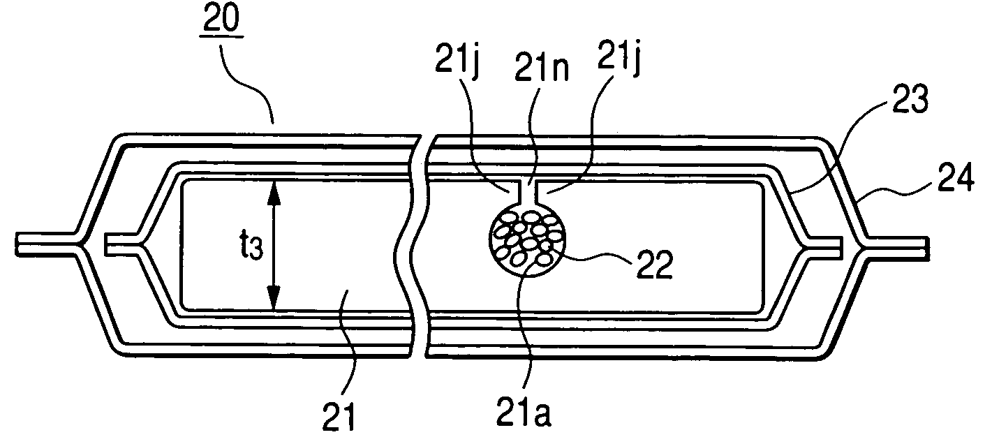
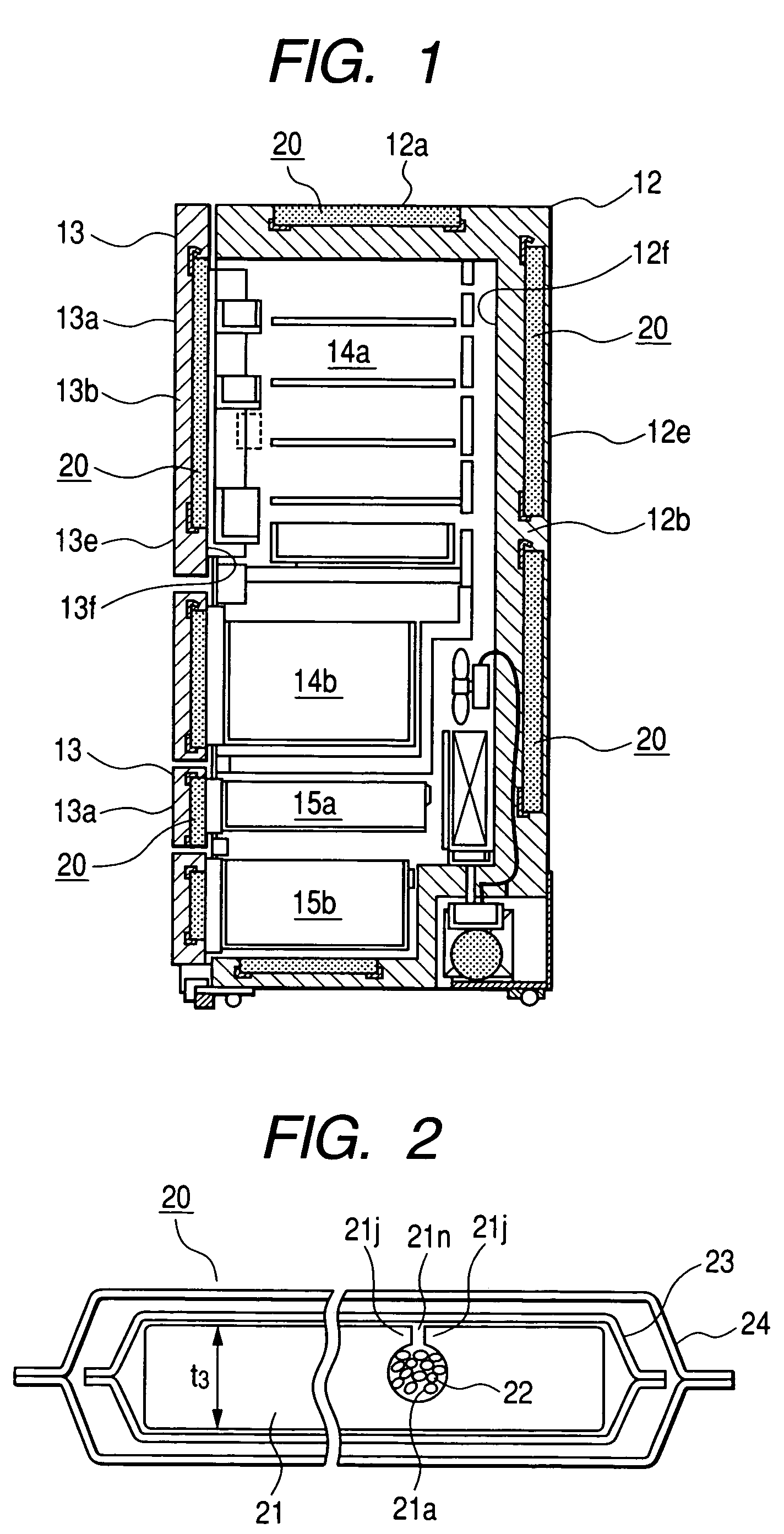
[0036]An embodiment of the present invention will be described in the following with reference to drawings. FIG. 1 is a vertical sectional view of principal parts of a refrigerator according to an embodiment of the present invention. FIG. 2 is an explanatory cross-sectional view of a vacuum insulation panel according to a first embodiment of the present invention. As shown in FIG. 1, a frame 12 of the refrigerator is provided with plural doors 13 which can open and close openings of the frame 12. In the frame 12, there are a chill compartment 14a, a vegetable compartment 14b, an ice compartment 15a, and a freezer compartment 15b. An insulation wall 12a of the frame 12 of the refrigerator is provided with vacuum insulation panels 20 being described later. The vacuum insulation panels 20 are set in space formed between an outer plate 12e and an inner plate 12f of the frame 12. In the space, they are disposed toward the outer plate 12e or toward the inner plate 12f. A foam insulation 1...

second embodiment

[0052]Next a second embodiment of the present invention will be explained with reference to FIGS. 5A to 5C. FIGS. 5A to 5C are explanatory diagrams showing core material processing according to the second embodiment of the present invention. FIG. 5A is a diagram for explaining first processing. FIG. 5B is a diagram for explaining second processing performed on the core material coming through the first processing shown in FIG. 5A. FIG. 5C is a diagram for explaining third processing performed on the core material coming through the second processing shown in FIG. 5B. It is a perspective view of a core material itself having undergone first compression, as being described later, in a process equivalent to the one illustrated in FIG. 4C. First, referring to FIG. 5A, reference numerals 21d, 21e, and 21f represent three layers of inorganic fiber core material provided with air circulation, with each layer shaped in a prescribed size and the three layers laminated as shown. The inorganic...

third embodiment

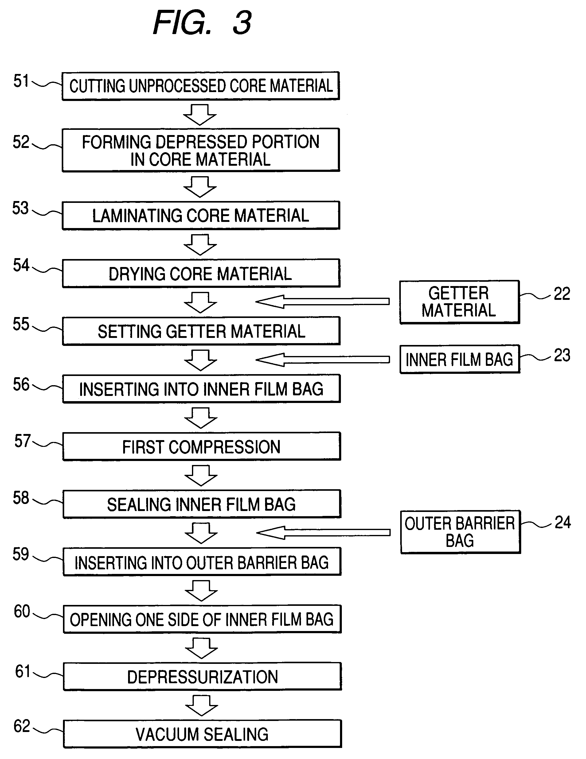
[0060]Next, a third embodiment of the present invention will be explained with reference to FIGS. 6A to 6C. FIGS. 6A to 6C are explanatory diagrams showing core material and inner film bag processing according the third embodiment of the present invention. This embodiment is an example in which the step 56 for insertion into an inner film bag, the step 57 for first compression and the step 58 for sealing the inner film bag are combined.

[0061]An inorganic fiber assembly 21′ to be made a core of a vacuum insulation panel is carried by a conveyor 33′ in a state of being placed between an upper portion and a lower portion of the conveyer. The distance between the upper portion and the lower portion of the conveyor 33′ is greater on the upstream side than on the downstream side of the conveyer. The inorganic fiber assembly 21′ is, therefore, caused to be vertically compressed while being carried by the conveyor 33′. When the inorganic fiber assembly 21′ carried in the direction shown by ...


PUM


Abstract

The invention provides a vacuum insulation panel to which moisture and gas do not easily adsorb while it is being processed or being in storage in an unfinished state. The vacuum insulation panel includes a core provided with air circulation, a getter material which adsorbs moisture and gas from the core, an inner film bag which accommodates the core and the getter material, and an outer barrier bag which accommodates the inner film bag. The getter material is filled in an incision provided on the surface of the core. To prevent the getter material from getting out of the incision, the opening of the incision is narrowed by evacuating air from the interior of the inner film bag and, concurrently, compressing the inner film bag and the core.

Description

CLAIM OF PRIORITY[0001]The present application claims priority from Japanese application serial JP 2004-297084 filed on Oct. 12, 2004, the content of which is hereby incorporated by reference into this application.FIELD OF THE INVENTION[0002]The present invention relates to a vacuum insulation panel, a refrigerator incorporating the same, and a method for producing the same.BACKGROUND OF THE INVENTION[0003]A vacuum insulation panel and a refrigerator using a vacuum insulation panel is disclosed in Japanese Patent Laid-Open No. 2004-3534. The vacuum insulation panel described in FIG. 1 and the specification of Japanese Patent Laid-Open No. 2004-3534 has a depressed portion for holding a getter material. The depressed portion is formed on a joint surface of at least one of plural boards made of inorganic fiber shaped by heating and pressurization. Such an arrangement is to prevent the getter material from projecting and damaging an outer cover of the vacuum insulation panel.[0004]FIG....

Claims


Application Information

Patent Timeline
Patent Type & Authority Patents(United States)
IPC IPC(8): F16L59/065
CPCF16L59/04F16L59/065Y10T428/24314Y10T428/231F25D2201/14F25D23/06F25D11/00F25D23/00
Inventor ECHIGOYA, WATARUARAKI, KUNINARIKUBOTA, TSUYOSHIMISEKI, TAKASHI
Owner HITACHI APPLIANCES INC
Why Eureka
Try Eureka