Electric discharge machining apparatus

a technology of electric discharge and machining equipment, which is applied in the direction of electrical-based machining electrodes, vibration holders, manufacturing tools, etc., can solve the problems of increasing the speed of machining the workpiece to be machined by electric discharge machining, and affecting the quality of machining workpieces, etc., to achieve the effect of reducing the amount of protrusion, preventing buckling and vibration, and shortening the tim

Inactive Publication Date: 2009-04-14
MITSUBISHI ELECTRIC CORP
View PDF25 Cites 10 Cited by
  • Summary
  • Abstract
  • Description
  • Claims
  • Application Information

AI Technical Summary

Benefits of technology

[0019]In this manner, this invention is constructed in such a way that the pressurized fluid is injected and supplied into the guide electrode that is shaped like a hollow bar and receives the small-diameter wire electrode to thereby feed the small-diameter wire electrode from inside the guide electrode to the electric discharge machining side. Hence, this invention produces the effect of being able to feed out the small-diameter wire electrode in the guide electrode automatically in a short time by the injecting force of pressurized fluid supplied into the guide electrode while keeping the shape of small-diameter wire electrode by the guide electrode shaped like a hollow bar without deforming the small-diameter wire electrode to yet be fed out. Moreover, because the small-diameter wire electrode fed out from inside the guide electrode is automatically held by the small-diameter wire electrode holding means, this invention produces the effect of preventing the buckling and vibration of the small-diameter wire electrode fed out from the guide electrode. Further, because the invention includes the small-diameter wire electrode holding means that automatically holds the small-diameter wire electrode fed out from inside the guide electrode as described above, the invention can decrease the amount of protrusion of the small-diameter wire electrode from the small-diameter wire electrode holding means to a workpiece to be machined and hence makes it possible for the small-diameter wire electrode protruding by the decreased amount of protrusion to be harder to buckle and vibrate. Hence, this invention produces the effect of realizing the electric discharge machining of making a hole of high circularity. Still further, since the invention can elongate the length of small-diameter wire electrode received in the guide electrode, the invention can elongate the timing when the small-diameter wire electrode is replaced because of consumption. For this reason, this invention produces the effect of shortening the total time required to replace the small-diameter wire electrode. As described above, this invention has the effect of shortening the time required to prepare machining at the time of performing the electric discharge machining of making a hole and the effect of making improvements in machining speed and in machining accuracy.

Problems solved by technology

However, the machining state of the workpiece to be machined by means of the electrode for machining may fluctuate irregularly.
Because the conventional electric discharge machining apparatuses are constructed in the above-mentioned manner, they present the following various problems.
However, the electric discharge machining apparatus disclosed in the patent document 1 does not describe anything about the function of feeding out the above-mentioned small-diameter wire automatically.
Moreover, according to the electric discharge machining apparatus disclosed in the patent document 1, the speed of machining the workpiece to be machined by the electric discharge machining can be increased but it takes time to correct the consumption of small-diameter wire electrode when the small-diameter wire electrode is used.
Hence, this raises a problem that in order to shorten total machining time, an automatic supply mechanism of the small-diameter wire electrode is required.
When an electrode replacing mechanism for replacing such a pipe electrode and its electrode holder in their entirety is applied to the electric discharge machining apparatus disclosed in the patent document 1, the high-speed-response driving ability of the pipe electrode is impaired.
This raises a problem that the sufficient effect of enhancing the speed and accuracy of electric discharge machining can not be expected.
Moreover, a new pipe electrode is long in length and hence is large in resistance, but because the pipe electrode is consumed and shortened by the electric discharge machining, the pipe electrode is gradually decreased also in resistance.
Hence, there is presented a problem that the quality of machining cannot be kept uniformly.
However, there is a possibility that the small-diameter wire electrode will be deformed, for example, in an ellipsoidal shape by a force that the rollers applies to the small-diameter wire electrode.
Hence, there is presented a problem that it is impossible to make a hole of high circularity.
For this reason, an operator needs to always control a machining state and needs to manually feed out the small-diameter wire electrode by the amount of consumption, which presents a problem that an electric discharge machining apparatus cannot be fully automated.
Moreover, because the small-diameter wire electrode applied to this electric discharge machining apparatus has a diameter of 0.1 mm, there is presented a problem that the electric discharge machining of making a fine hole by using a wire having a small diameter not larger than the diameter cannot be continuously performed.

Method used


Image

  • Electric discharge machining apparatus
  • Electric discharge machining apparatus
  • Electric discharge machining apparatus

Examples


embodiment 1

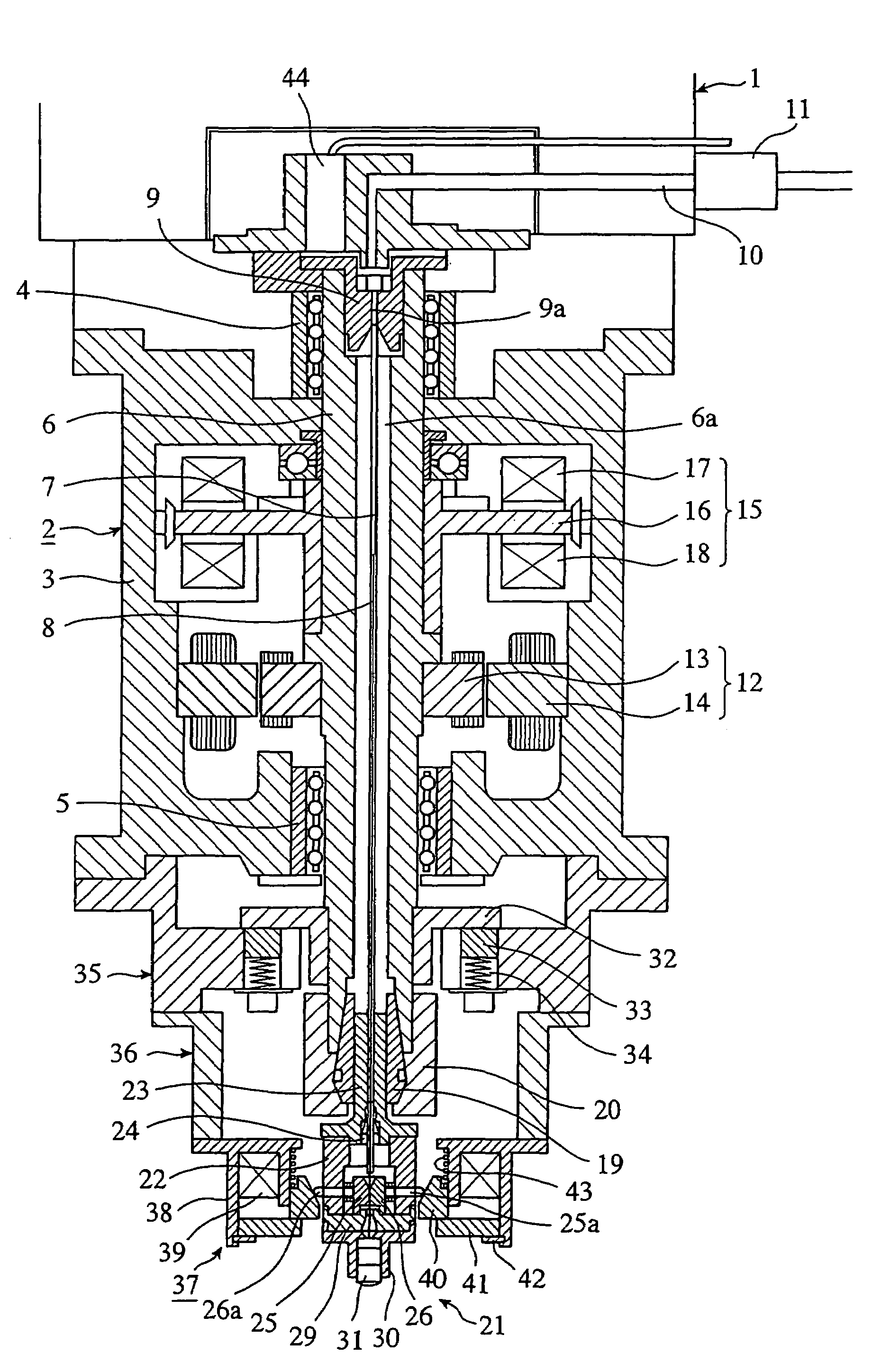
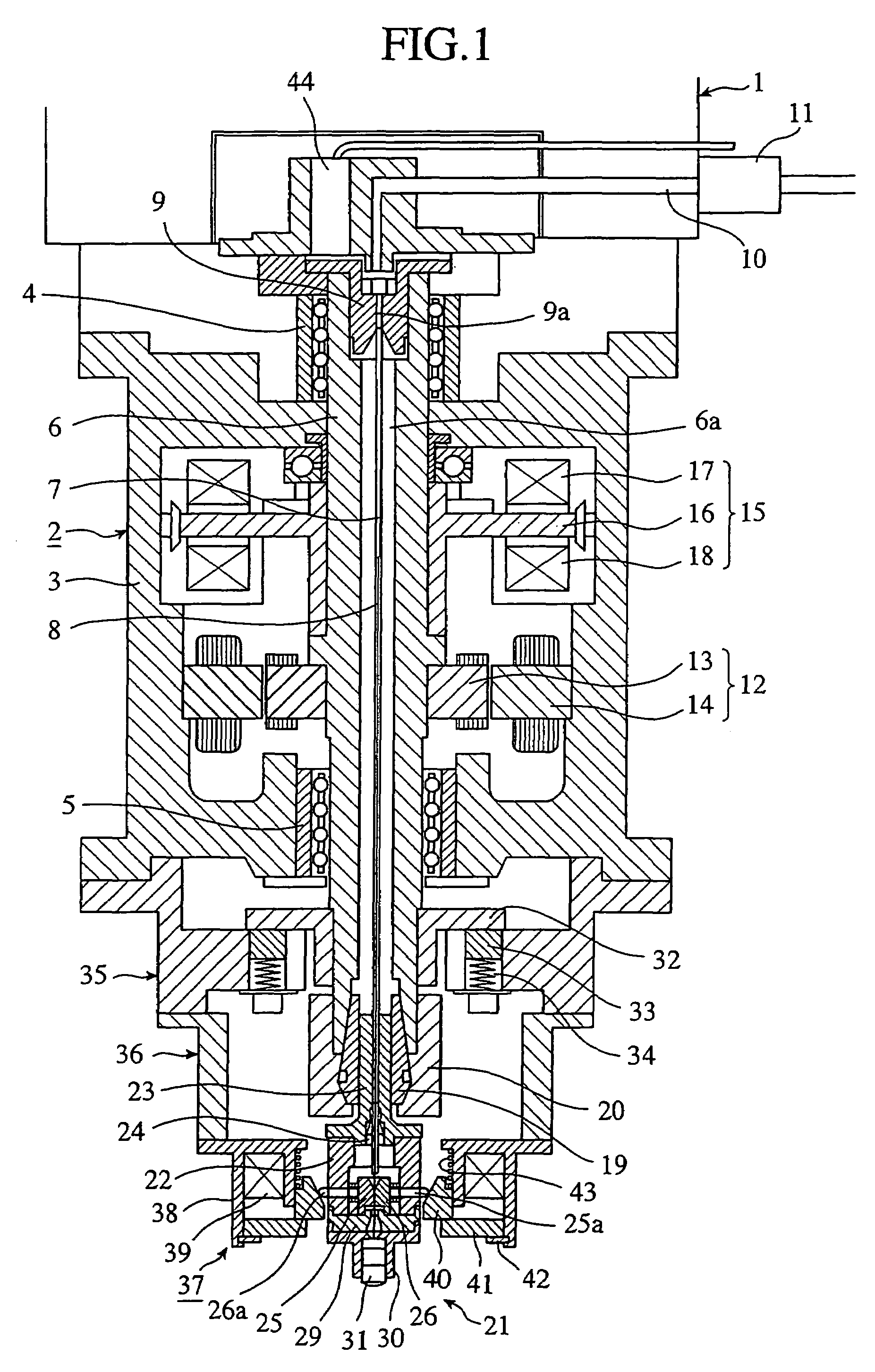
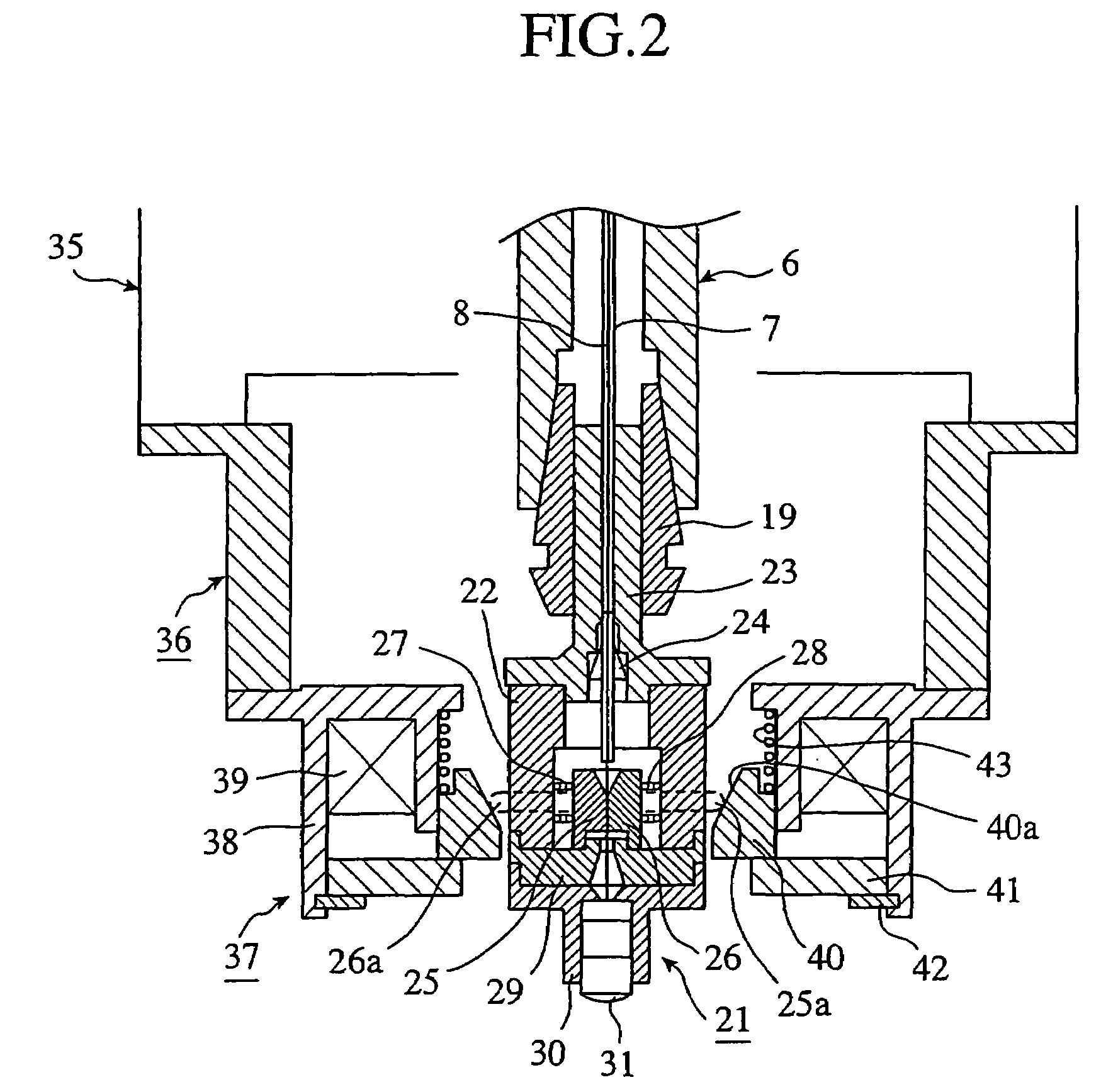
[0028]FIG. 1 is a cross-sectional view showing an electric discharge machining apparatus in accordance with embodiment 1 of this invention, FIG. 2 is an enlarged cross-sectional view of a main portion in FIG. 1, and FIG. 3 is a lateral cross-sectional view of a main portion in FIG. 2.

[0029]In FIG. 1, the main shaft head 1 of the electric discharge machining apparatus is mounted with an electrode driving unit 2 of high-speed responsivity. This electrode driving unit 2 includes a housing 3 serving as a main body of this unit and a driving shaft 6 mounted in a central portion in this housing 3 in such a way as to be rotatable and movable in an axial direction via upper and lower bearings 4, 5. A bearing such as a rotary sliding bush to allow the driving shaft 6 to move in the axial direction (direction of thrust) is applied as the bearings 4, 5. The driving shaft 6 has a central through hole 6a and has a guide electrode 7 shaped like a hollow bar (shaped like a pipe) inserted into this...

embodiment 2

[0058]FIG. 4(A) is a front view showing a guide electrode inserting jig in accordance with embodiment 2 of this invention, and FIG. 4(B) is a cross-sectional view in a radial direction in FIG. 4(A), and FIG. 4(C) is a cross-sectional view in an axial direction in FIG. 4(A).

[0059]A guide electrode inserting jig 50 in accordance with this embodiment 2 is such that is used in the case of loading the small-diameter wire electrode 8 and the guide electrode 7 into the small-diameter wire electrode holding unit 21 of the electric discharge machining apparatus in accordance with the above-mentioned embodiment 1. That is, in the electric discharge machining apparatus of the above-mentioned embodiment 1, in order to pass the guide electrode 7 through the rubber bush 24 in the small-diameter wire electrode holding unit 21 and to insert the guide electrode 7 into the central through hole 6a of driving shaft 6 and to insert and retain the guide electrode 7 into and by the upper guide electrode h...

embodiment 3

[0065]FIG. 5(A) is a cross-sectional view, in an axial direction, showing a guide electrode inserting jig in accordance with embodiment 3 of this invention, and FIG. 5(B) is a cross-sectional view in a radial direction in FIG. 5(A).

[0066]A guide electrode inserting jig 100 in accordance with this embodiment 3 is such that is used in the case of loading the small-diameter wire electrode 8 and the guide electrode 7 into the small-diameter wire electrode holding unit 21 of the electric discharge machining apparatus in accordance with the above-mentioned embodiment 1. That is, in the electric discharge machining apparatus of the above-mentioned embodiment 1, in order to pass the guide electrode 7 through the rubber bush 24 in the small-diameter wire electrode holding unit 21 and then to insert the guide electrode 7 into the central through hole 6a of driving shaft 6 to thereby insert and retain the guide electrode 7 into and by the upper guide electrode holder 9, the guide electrode 7 n...


PUM

PropertyMeasurementUnit
diameteraaaaaaaaaa
diameteraaaaaaaaaa
lengthaaaaaaaaaa

Abstract

An electric discharge machining apparatus includes a guide electrode that is tubular and receives a small-diameter wire electrode for electric discharge machining. The small-diameter wire electrode can freely slide within the guide electrode. A guide electrode holder holds the guide electrode at a specified position. Pressurized fluid is supplied into the guide electrode to feed the small-diameter wire electrode from the guide electrode. A small-diameter wire electrode holder automatically releases and grasps the small-diameter wire electrode in response to starting and stopping of the pressurized fluid supply, respectively.

Description

TECHNICAL FIELD[0001]The present invention relates to an electric discharge machining apparatus that makes a hole in a workpiece to be machined and, in particular, to an electric discharge machining apparatus that is suitable for use in making a fine hole in a workpiece to be machined by means of electric discharge machining using a small-diameter wire as an electrode.BACKGROUND ART[0002]Generally, in this kind of electric discharge machining apparatus, an electrode for machining and a workpiece to be machined are arranged in machining liquid and voltage is applied therebetween them to develop electric discharge to make a hole in the workpiece to be machined by electric discharge machining. In order to make a hole of a desired shape while keeping a stable machining state, the electric discharge machining apparatus is provided with a driving unit for adjusting the position of the electrode for machining or the workpiece to be machined.[0003]A command to the driving unit adjusts the p...

Claims


Application Information

Patent Timeline
Patent Type & Authority Patents(United States)
IPC IPC(8): B23H1/04B23H7/26B23H9/14B23H1/10B23H7/30B23H7/36
CPCB23H1/10B23H7/265B23H7/36B23H9/14B23H2400/10
Inventor MIYAKE, HIDETAKANAKAGAWA, TAKAYUKIIMAI, YOSHIHITO
Owner MITSUBISHI ELECTRIC CORP
Why Eureka
Try Eureka