Electric discharge machining apparatus

Inactive Publication Date: 2007-05-10
MITSUBISHI ELECTRIC CORP
View PDF10 Cites 17 Cited by
  • Summary
  • Abstract
  • Description
  • Claims
  • Application Information

AI Technical Summary

Benefits of technology

[0019] In this manner, this invention is constructed in such a way that the pressurized fluid is injected and supplied into the guide electrode that is shaped like a hollow bar and receives the small-diameter wire electrode to thereby feed the small-diameter wire electrode from inside the guide electrode to the electric discharge machining side. Hence, this invention produces the effect of being able to feed out the small-diameter wire electrode in the guide electrode automatically in a short time by the injecting force of pressurized fluid supplied into the guide electrode while keeping the shape of small-diameter wire electrode by the guide electrode shaped like a hollow bar without deforming the small-diameter wire electrode to yet be fed out. Moreover, because the small-diameter wire electrode fed out from inside the guide electrode is automatically held by the small-diameter wire electrode holding means, this invention produces the effect of preventing the buckling and vibration of the small-diameter wire electrode fed out from the guide electrode. Further, because the invention includes the small-diameter wire electrode holding means that automatically hold

Problems solved by technology

However, the machining state of the workpiece to be machined by means of the electrode for machining may fluctuate irregularly.
Because the conventional electric discharge machining apparatuses are constructed in the above-mentioned manner, they present the following various problems.
However, the electric discharge machining apparatus disclosed in the patent document 1 does not describe anything about the function of feeding out the above-mentioned small-diameter wire automatically.
Moreover, according to the electric discharge machining apparatus disclosed in the patent document 1, the speed of machining the workpiece to be machined by the electric discharge machining can be increased but it takes time to correct the consumption of small-diameter wire electrode when the small-diameter wire electrode is used.
Hence, this raises a problem that in order to shorten total machining time, an automatic supply mechanism of the small-diameter wire electrode is required.
When an electrode replacing mechanism for replacing such a pipe electrode and its electrode holder in their entirety is applied to the electric discharge machining apparatus disclosed in the patent document 1, the high-speed-response driving ability of the pipe electrode is impaired.
This raises a problem that the sufficient ef

Method used


Image

  • Electric discharge machining apparatus
  • Electric discharge machining apparatus
  • Electric discharge machining apparatus

Examples


embodiment 1

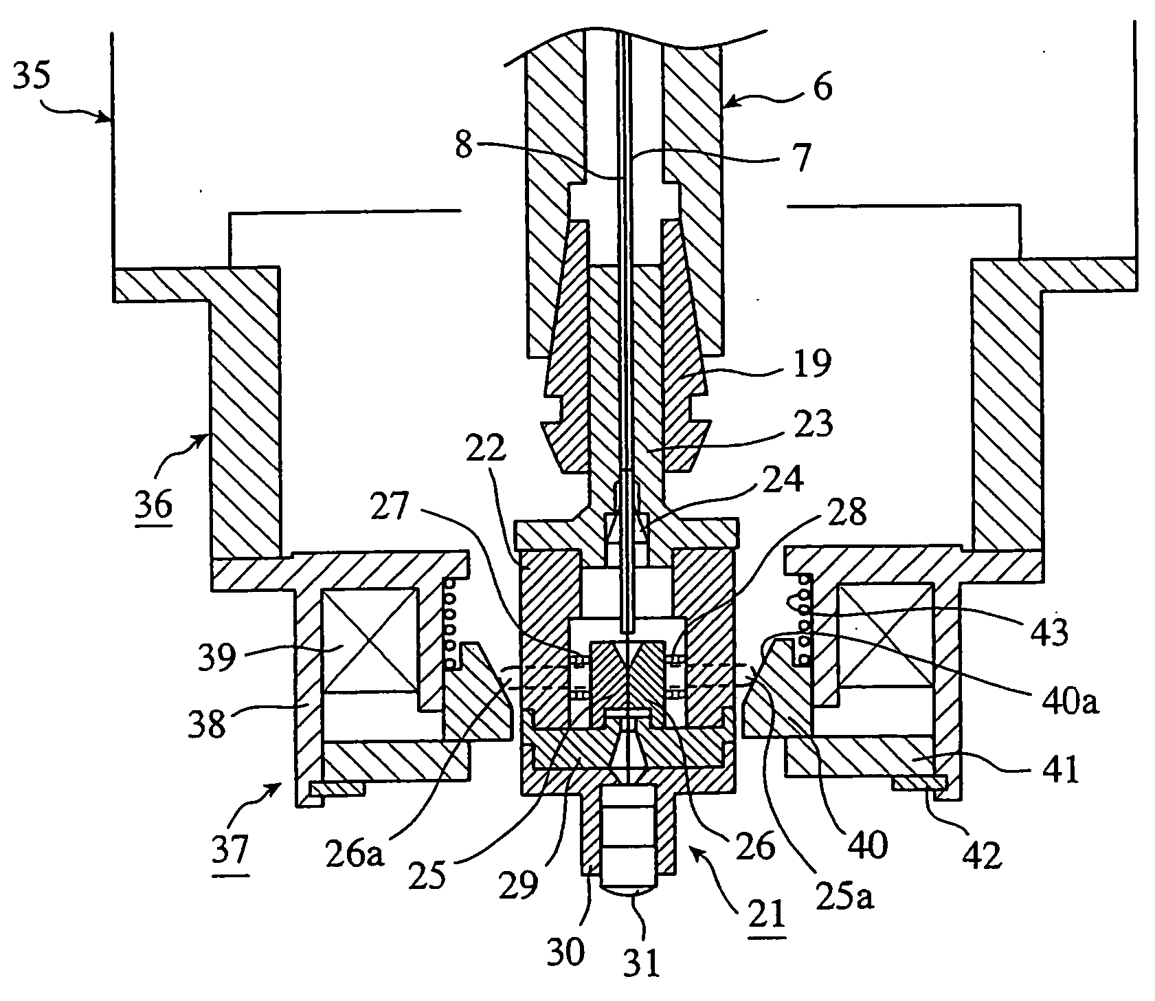
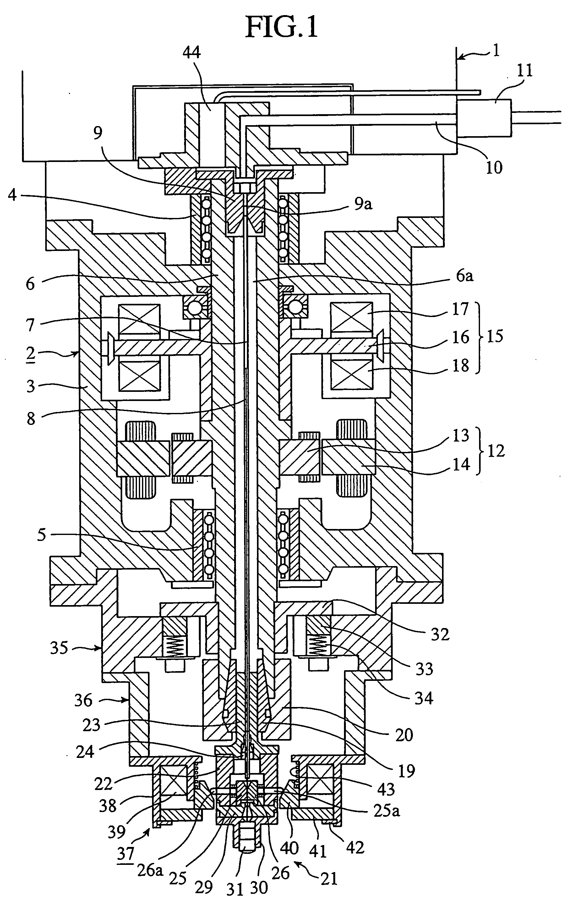
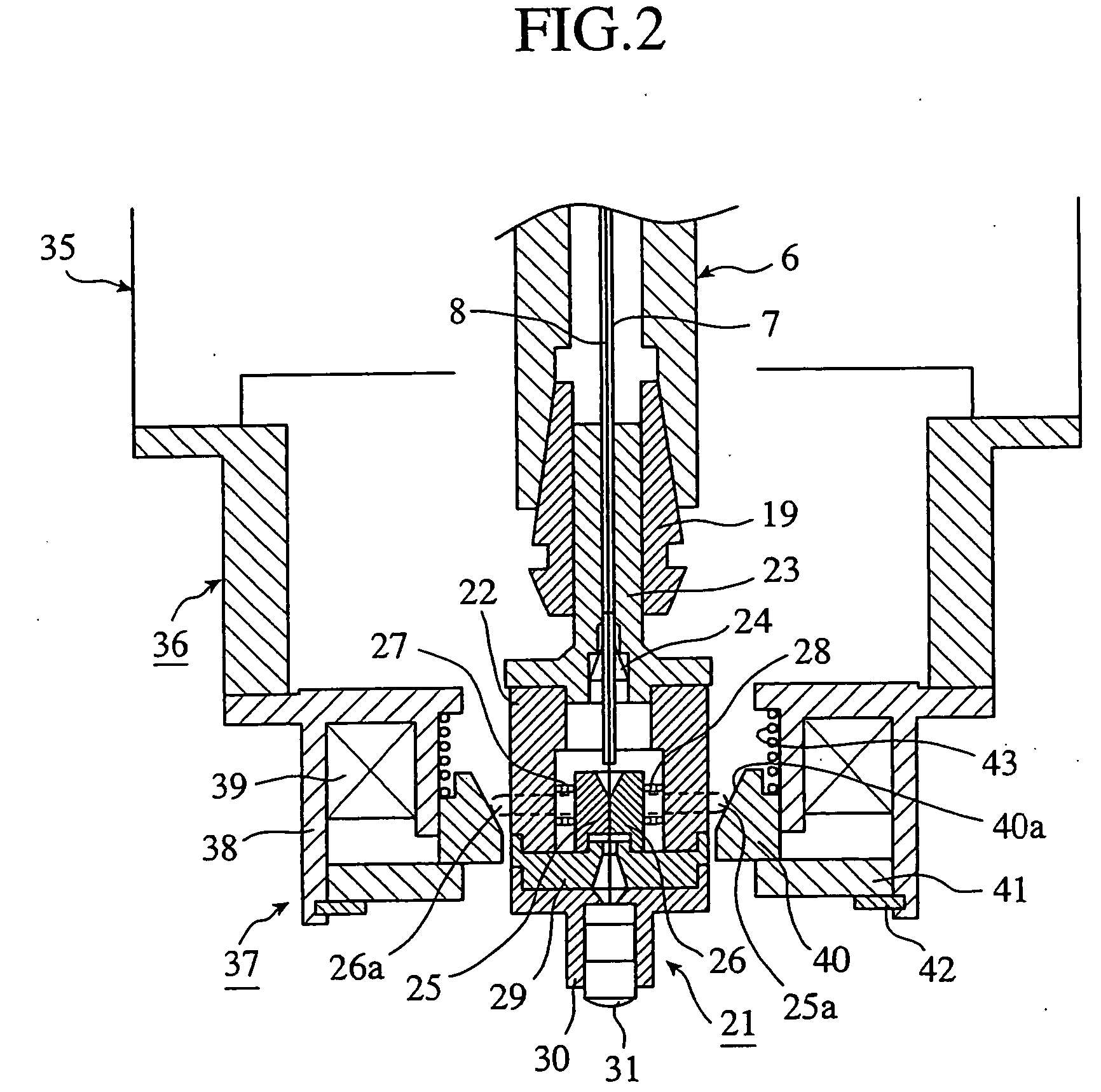
[0028]FIG. 1 is a cross-sectional view showing an electric discharge machining apparatus in accordance with embodiment 1 of this invention, FIG. 2 is an enlarged cross-sectional view of a main portion in FIG. 1, and FIG. 3 is a lateral cross-sectional view of a main portion in FIG. 2.

[0029] In FIG. 1, the main shaft head 1 of the electric discharge machining apparatus is mounted with an electrode driving unit 2 of high-speed responsivity. This electrode driving unit 2 includes a housing 3 serving as a main body of this unit and a driving shaft 6 mounted in a central portion in this housing 3 in such a way as to be rotatable and movable in an axial direction via upper and lower bearings 4, 5. A bearing such as a rotary sliding bush to allow the driving shaft 6 to move in the axial direction (direction of thrust) is applied as the bearings 4, 5. The driving shaft 6 has a central through hole 6a and has a guide electrode 7 shaped like a hollow bar (shaped like a pipe) inserted into th...

embodiment 2

[0058]FIG. 4(A) is a front view showing a guide electrode inserting jig in accordance with embodiment 2 of this invention, and FIG. 4(B) is a cross-sectional view in a radial direction in FIG. 4(A), and FIG. 4(C) is a cross-sectional view in an axial direction in FIG. 4(A).

[0059] A guide electrode inserting jig 50 in accordance with this embodiment 2 is such that is used in the case of loading the small-diameter wire electrode 8 and the guide electrode 7 into the small-diameter wire electrode holding unit 21 of the electric discharge machining apparatus in accordance with the above-mentioned embodiment 1. That is, in the electric discharge machining apparatus of the above-mentioned embodiment 1, in order to pass the guide electrode 7 through the rubber bush 24 in the small-diameter wire electrode holding unit 21 and to insert the guide electrode 7 into the central through hole 6a of driving shaft 6 and to insert and retain the guide electrode 7 into and by the upper guide electrode...

embodiment 3

[0065]FIG. 5(A) is a cross-sectional view, in an axial direction, showing a guide electrode inserting jig in accordance with embodiment 3 of this invention, and FIG. 5(B) is a cross-sectional view in a radial direction in FIG. 5(A).

[0066] A guide electrode inserting jig 100 in accordance with this embodiment 3 is such that is used in the case of loading the small-diameter wire electrode 8 and the guide electrode 7 into the small-diameter wire electrode holding unit 21 of the electric discharge machining apparatus in accordance with the above-mentioned embodiment 1. That is, in the electric discharge machining apparatus of the above-mentioned embodiment 1, in order to pass the guide electrode 7 through the rubber bush 24 in the small-diameter wire electrode holding unit 21 and then to insert the guide electrode 7 into the central through hole 6a of driving shaft 6 to thereby insert and retain the guide electrode 7 into and by the upper guide electrode holder 9, the guide electrode 7...


PUM

PropertyMeasurementUnit
Diameteraaaaaaaaaa

Abstract

An electric discharge machining apparatus includes: a guide electrode (7) that is shaped like a hollow bar and receives a small-diameter wire electrode (8) for electric discharge machining in such a way that the small-diameter electrode can freely slide and; guide electrode holding means (9, 19, 20) that holds this guide electrode (7) at a specified position; pressurized fluid supply means (10, 11) that supplies pressurized fluid into the guide electrode (7) to feed out the small-diameter wire electrode (8) from inside the guide electrode (7) to an electric discharge machining side; and small-diameter wire electrode holding means (21) that automatically holds the small-diameter wire electrode (8) fed out of the guide electrode (7).

Description

TECHNICAL FIELD [0001] The present invention relates to an electric discharge machining apparatus that makes a hole in a workpiece to be machined and, in particular, to an electric discharge machining apparatus that is suitable for use in making a fine hole in a workpiece to be machined by means of electric discharge machining using a small-diameter wire as an electrode. BACKGROUND ART [0002] Generally, in this kind of electric discharge machining apparatus, an electrode for machining and a workpiece to be machined are arranged in machining liquid and voltage is applied therebetween them to develop electric discharge to make a hole in the workpiece to be machined by electric discharge machining. In order to make a hole of a desired shape while keeping a stable machining state, the electric discharge machining apparatus is provided with a driving unit for adjusting the position of the electrode for machining or the workpiece to be machined. [0003] A command to the driving unit adjust...

Claims


Application Information

Patent Timeline
IPC IPC(8): B23H1/04B23H7/26B23H1/10B23H7/30B23H7/36B23H9/14
CPCB23H1/10B23H7/265B23H7/36B23H9/14B23H2400/10
Inventor MIYAKE, HIDETAKANAKAGAWA, TAKAYUKIIMAI, YOSHIHITO
Owner MITSUBISHI ELECTRIC CORP
Why Eureka
Try Eureka