Header with high speed sickle drives for a plant cutting machine

a cutting machine and high-speed technology, applied in the direction of mowers, agriculture tools and machines, mowers, etc., can solve the problems of requiring a lower operating speed, large mass, and relatively short blade assemblies of these sickles, and achieve the effect of increasing ground speed, net overall force and vibrations

Inactive Publication Date: 2009-04-21
BLUE LEAF I P INC
View PDF21 Cites 83 Cited by
  • Summary
  • Abstract
  • Description
  • Claims
  • Application Information

AI Technical Summary

Benefits of technology

[0007]According to a preferred aspect of the invention, the header includes an elongate structure having a first end portion, a second end portion opposite the first end portion, an elongate forward edge portion extending between the first and second end portions, and an at least generally upwardly facing floor extending along the elongate forward edge portion between the first and second end portions. The header includes an elongate first knife assembly supported by the structure adjacent to a first portion of the forward edge portion thereof for longitudinal movement therealong, and an elongate second knife assembly supported by the structure adjacent to a second portion of the forward edge portion thereof for longitudinal movement therealong in generally end to end relation to the first knife assembly. A first sickle drive mechanism is also supported on the structure and includes a first epicyclic drive connected in driving relation to the first knife assembly and operable for reciprocatingly moving the first knife assembly relative to and along the first forward edge portion of the structure, and a second epicyclic drive connected in driving relation to the second knife assembly and operable for reciprocatingly moving the second knife assembly relative to and along the second forward edge portion of the structure. The first sickle drive mechanism is preferably disposed at least partially beneath a portion of the floor spaced from the first and second and portions of the structure, such that cut crop material will flow easily, and uninterrupted thereover.
[0009]According to another preferred aspect of the invention, the knife assemblies are each from about 7 feet to about 12 feet in width. And, according to another preferred aspect, each of the epicyclic drives is operable for reciprocatingly moving the knife assembly connected thereto at a speed of at least about 1600 strokes per minute, and more preferably within a range of from about 1600 to about 2000 strokes per minute. As a result, greater ground speeds can be achieved.
[0010]According to still another preferred aspect of the invention, the two epicyclic drives of each sickle drive mechanism are mounted in side by side relation, and are connected in timed reciprocatingly driving relation to the two knife assemblies, respectively, for simultaneously moving the knife assemblies reciprocatingly in opposite sideward directions. The timing causes the elements of the respective drives to eccentrically rotate in timed relation, such that radial forces generated by imbalances of the respective elements are at least substantially cancelled, resulting in the net overall forces and vibrations emanating from the two drives and knife assemblies being greatly reduced or even substantially eliminated.

Problems solved by technology

However, the knife assemblies of these sickles are relatively short, having maximum widths of only about 9 feet.
However, it also a disadvantage for wider headers, as it requires the knife assemblies to have a length of at least one half the width of the header, and thus a greater mass, which in turn, requires a lower operating speed.

Method used


Image

  • Header with high speed sickle drives for a plant cutting machine
  • Header with high speed sickle drives for a plant cutting machine
  • Header with high speed sickle drives for a plant cutting machine

Examples


Embodiment Construction

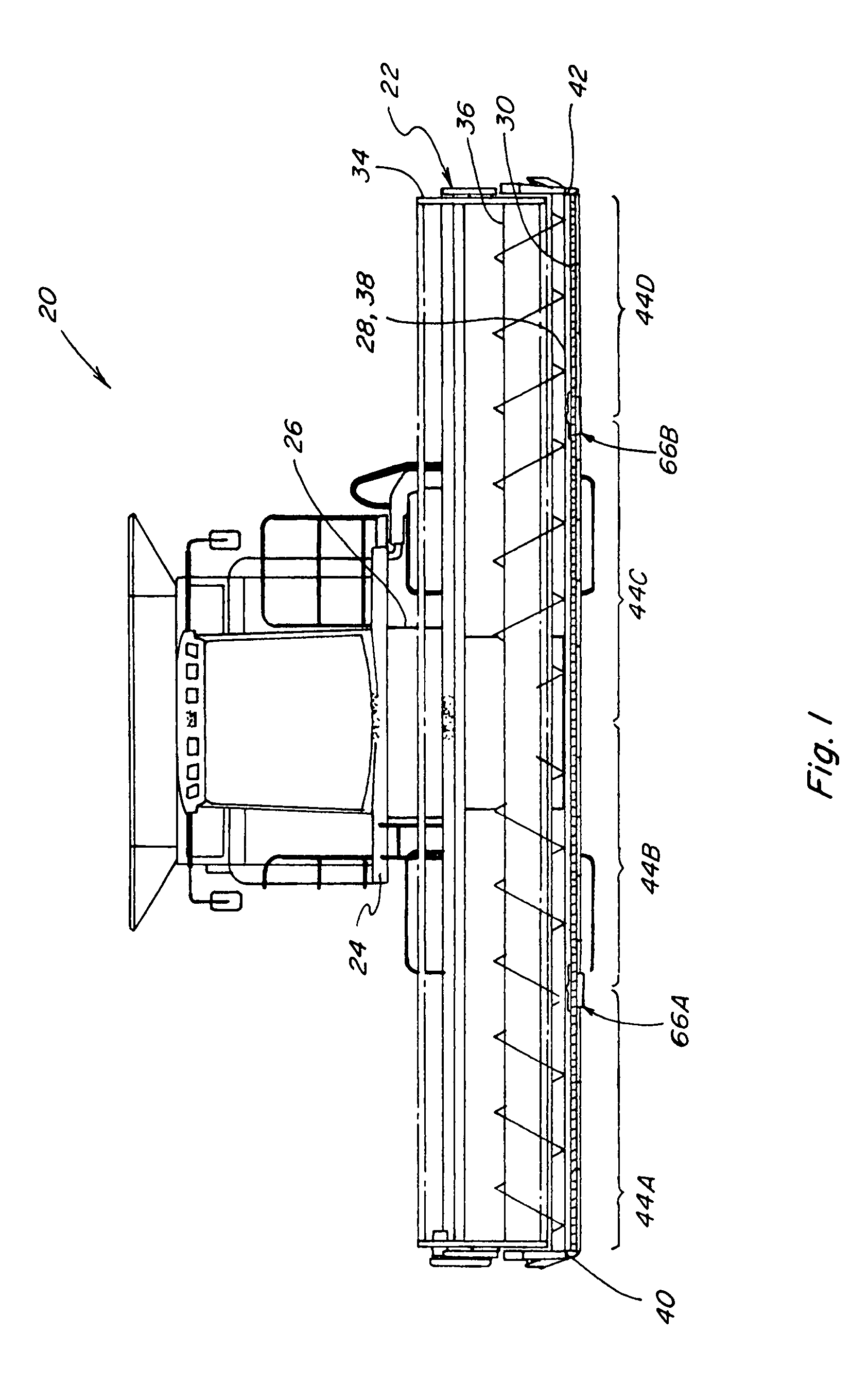
[0036]Turning now to the drawings wherein a preferred embodiment of the invention are shown, in FIG. 1, a conventional, well known agricultural cutting machine, which is a combine 20, is shown including a header 22. Header 22 is shown supported in the conventional, well-known manner on a forward end 24 of combine 20, and is operable for cutting or severing crops such as, but not limited to, small grains such as wheat and soybeans, and inducting the severed crops into a feeder 26 for conveyance into combine 20 for threshing and cleaning, in the well known manner, as combine 20 moves forwardly over a field.

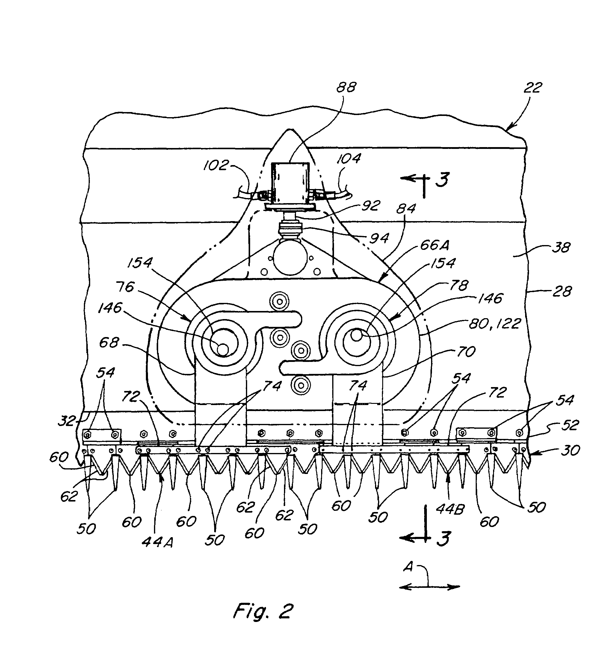
[0037]Referring also to FIGS. 2 and 3, header 22 includes a pan or floor 28 which is supported in desired proximity to the surface of the field during the harvesting operation, and an elongate, sidewardly extending sickle 30 along a forward edge portion 32 of floor 28, sickle 30 being operable for severing the crop for induction into header 22, as will be explained. Header 22 additi...


PUM


Abstract

A header for a plant cutting machine uses a plurality of compact sickle drive mechanisms incorporated into or beneath a floor or pan of the header at a location between and spaced from the sides or ends of the header, each of which mechanisms can be configured for reciprocatingly driving two knife assemblies disposed in end to end relation, in opposite directions, such that potentially vibratory forces, including those generated by the moving masses of the knife assemblies, at least substantially cancel one another and thus are not transferred to structure of the header. As a result, the knife assemblies can each be relatively short, to lessen the mass thereof so as to be capable of being operated at higher speeds, to enable operation of the header at faster ground speeds.

Description

TECHNICAL FIELD[0001]This invention relates generally to a header for a plant cutting machine such as a combine or a windrower, and more particularly, to a header including a plurality of compact epicyclic drive mechanisms disposed at locations along the width thereof and connected in driving relation to knife assemblies of a sickle of the header, the drive mechanisms being adapted for high speed operation, for enabling operation of the header at high ground speed.BACKGROUND ART[0002]Agricultural combines have increased in capacity to harvest large quantities of crop material to such a degree that it is becoming desirable to have the capability to increase the ground speed of the combine to match header productivity with the increased combine capacity. Generally, the maximum ground speed of a header is considered to be the greatest speed at which the cutting sickle of the header will not strip and leave crop on the field. This, in turn, is a function of the speed of reciprocating mo...

Claims


Application Information

Patent Timeline
Patent Type & Authority Patents(United States)
IPC IPC(8): A01D34/02A01D34/30
CPCA01D34/30A01D41/14
Inventor PRIEPKE, EDWARD H.
Owner BLUE LEAF I P INC
Why Eureka
Try Eureka