Hybrid vehicle with combustion engine/electric motor drive

a hybrid vehicle and electric motor technology, applied in the direction of engine-driven generators, electric devices, vehicular safety arrangements, etc., can solve the problems of increasing engine cost, affecting the safety of passengers,

Inactive Publication Date: 2009-04-21
OSHKOSH CORPORATION
View PDF166 Cites 172 Cited by
  • Summary
  • Abstract
  • Description
  • Claims
  • Application Information

AI Technical Summary

Problems solved by technology

While this type of drive train is highly reliable, efficient based upon mature technology, it is relatively expensive in comparison to the other components of the vehicle.
Additionally, cost effective transmissions typically require engine oversizing to provide suitable vehicle speed surges.
Thus, to save transmission cost, there is an increase in engine cost and vise versa.
However, these types of drives have proven to be too inefficient to be practical.

Method used


Image

  • Hybrid vehicle with combustion engine/electric motor drive
  • Hybrid vehicle with combustion engine/electric motor drive
  • Hybrid vehicle with combustion engine/electric motor drive

Examples


Embodiment Construction

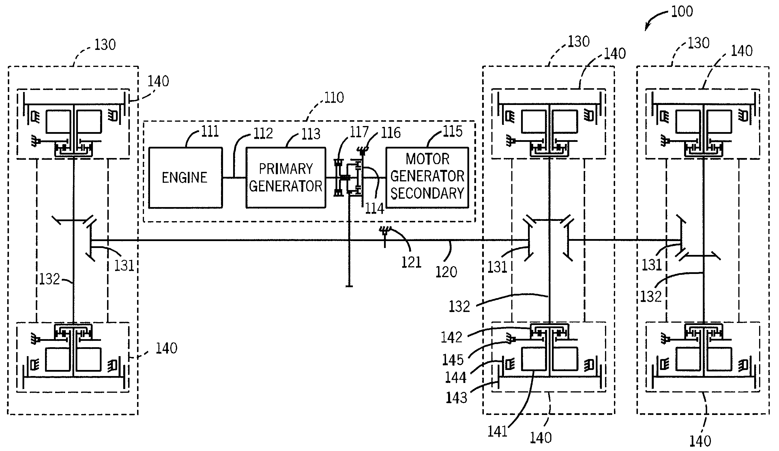
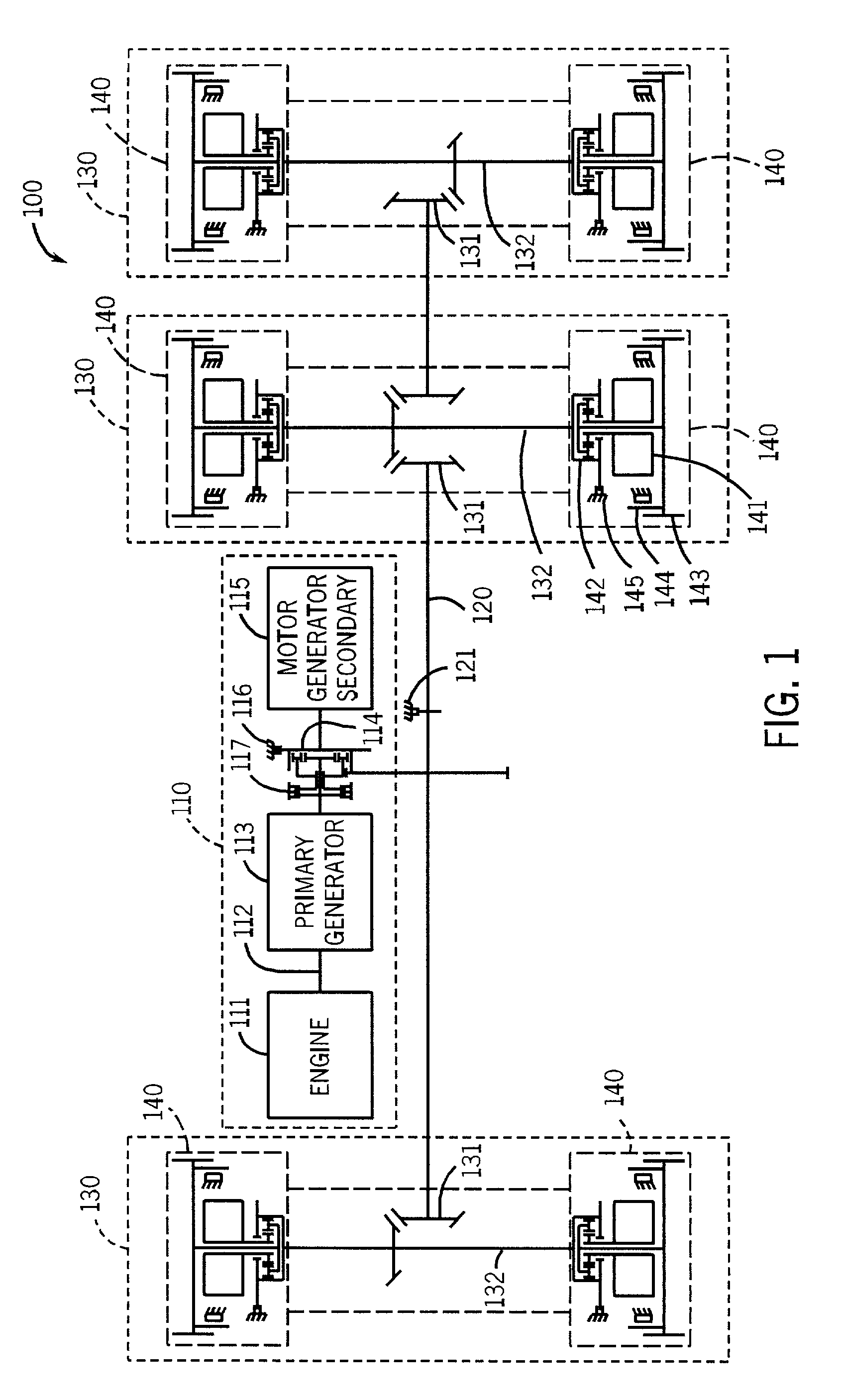
[0022]FIG. 1 is a top-down view of the driveline for a multi-axle vehicle 100. The driveline can includes a power assembly 110, a drive shaft 120, and at least one hybrid drive axle assembly 130.

[0023]According to an exemplary embodiment, power assembly 110 can include an prime mover 111, a prime mover output shaft 112, a primary generator 113, a power divider planetary gear 114, a secondary generator 115, a secondary generator brake 116, and a prime mover clutch 117. Prime mover 111 can be any source of rotational mechanical energy which is derived from a stored energy source such as a liquid or gaseous fuel. Examples are an internal combustion gas powered engine, a diesel engine, turbines, fuel cell driven motors, an electric motor, or any other type of motor capable of providing rotational mechanical energy to prime mover output shaft 112.

[0024]Prime mover output shaft 112 can be coupled to primary generator 113 so as to provide power to primary generator 113. Primary generator 1...


PUM


Abstract

A vehicle including a prime mover, a generator mechanically coupled to the prime mover, a first multi-input drive unit having at least first and second rotational inputs and at least one rotational output wherein the first rotational input is coupled to the prime mover, a first electric motor mechanically coupled to the second rotational input and electrically coupled to the generator and a first pair of vehicle drive wheels coupled to the rotational output.

Description

FIELD OF THE INVENTION[0001]The present invention relate to a drive system for a vehicle. In particular, the present invention relates to a work vehicle driven alternatively and in combination by a primary motor and at least one electric motor.BACKGROUND OF THE INVENTION[0002]Typical vehicles whether automobiles, fire trucks, garbage trucks, cement mixers, multiwheel drive trucks, military transport trucks, etc. include a combustion engine mechanically coupled to the driven wheels. This coupling typically takes the form of a clutch or torque converter coupled to a multispeed transmission which is coupled to the driven wheels. More specifically, the driven wheels are usually driven in pairs through a differential coupled to the transmission by an appropriate drive train e.g. drive shaft, angle drive, etc.[0003]While this type of drive train is highly reliable, efficient based upon mature technology, it is relatively expensive in comparison to the other components of the vehicle. Addi...

Claims


Application Information

Patent Timeline
Patent Type & Authority Patents(United States)
IPC IPC(8): B60K1/00B60C23/00B60K6/365B60K6/442B60K6/52B60W10/02B60W10/30H02J7/14
CPCB60K6/365B60K6/52B60K17/046B60L1/003B60L11/123B60L11/14B60W10/02B60W10/30B60K6/442Y02T10/7077B60L2260/26B60L2260/28B60W2300/126B60W2300/17B60W2300/18B60Y2200/14B60Y2200/144B60Y2200/41Y02T10/6217Y02T10/6234Y02T10/6265B60L50/61B60L50/16Y02T10/62Y02T10/7072Y02T10/70B60W30/18063
Inventor MORROW, JON J.YAKES, CHRISTOPHER K.
Owner OSHKOSH CORPORATION
Why Eureka
Try Eureka