Hand-held drive-in tool

a drive-in tool and hand-held technology, applied in the direction of manufacturing tools, portable drilling machines, transportation and packaging, etc., can solve the problems of increasing the cost of controlling the pivotal out spindle, and the increase of the cost of the drive-in tool

Active Publication Date: 2009-04-21
HILTI AG
View PDF12 Cites 28 Cited by
  • Summary
  • Abstract
  • Description
  • Claims
  • Application Information

AI Technical Summary

Benefits of technology

[0010]This and other objects of the present invention, which will become apparent hereinafter, are achieved by providing in a drive-in tool of the type discussed above, a sliding nut supported on the threaded spindle without a possibility of rotation thereabout but with a possibility of an axial displacement therealong, with the sliding nut being axially displaceable, upon actuation of the motor of the tensioning device by a control unit of the drive-in tool, between a first end position and a second end position and being displaceable, during a loading cycle, from the first end position to a second end position for displacing the driving spring into the loading position of the driving spring, and being subsequently displaceable from the second end position thereof into the first end position to provide for displacement of the driving spring into its release position. Thereby, the sliding nut is again in its initial position before a drive-in process is initiated, and the path for the driving spring is free. In case, the driving spring is loaded indirectly, via the drive-in ram, when the sliding nut cooperates with the drive-in ram, the drive-in ram can likewise be displaced to its initial position with the displacement of the sliding nut to its initial position. A complicated mechanics for the return displacement of threaded spindle is not any more necessary. Likewise, the problem of a chipped edge of the thread of the threaded spindle is eliminated.
[0011]It is advantageous, when the sliding nut is provided with at least one ball that serves as thread engagement means for engaging the threaded spindle. With formation of the sliding nut as a ball nut, the frictional and energy losses, which occur during displacement of the drive-in ram against the driving spring, can be noticeably reduced.
[0012]It is further advantageous when a first control conductor connects the locking device with the control unit, and a second control conductor connects the motor of the tensioning device with the control unit. Thereby, it becomes possible, to use the locking device for controlling reversing of the direction of rotation of the motor of the tensioning device in order to effect displacement of the sliding nut to its first, initial end position, e.g., when the pawl of the locking device engages, at the end of the loading movement of the tensioning device, the locking surface on the drive-in ram, generating a control signal. Alternatively, the reversing of the rotational direction of the motor can take place when the motor load reaches a predetermined value, e.g., when the driving spring (and also the drive-in ram, as the case may be) reaches its loaded position.
[0013]A technically simple solution of retention of the sliding nut against rotation is achieved by providing a guide element along which the sliding nut can be displaced without a possibility of rotation.
[0014]Advantageously, there is provided at least one damping member for braking movement of the drive-in ram in a drive-in direction, which is spaced from a first stop of the drive-in ram, with which the damping member cooperates, by an axial distance that is smaller than an axial distance by which the sliding nut is spaced, in its first end position from a stop of the drive-in ram which is located opposite the sliding nut. Thereby, an impact of the drive-in ram, which is displaceable in the drive-in direction, on the sliding nut that occupies its first end position, at the end of the drive-in process, is prevented. The drive-in ram impacts only the damping member. This increases the service life of the sliding nut.
[0015]A compact structure is obtained when the axis of the output shaft of the motor of the tensioning device extends parallel to a rotational axis of the threaded spindle, and the motor is located between planes defined, respectively, by end surfaces of the threaded spindle.

Problems solved by technology

The drawback of the drive-in tool, which is disclosed in U.S. Pat. No. 3,810,572, consists in a very complex arrangement of the three sleeves, which increases the costs of the drive-in tool, on one hand and, on the other hand, upon actuation of the drive-in tool, the entire force of the driving spring is applied, in a short time, to a very small surface on the edge of the thread where the last locking ball has been released.
This leads to a danger of the thread edge being chipped.
The drawback of the drive-in tool of DE 32 37 087 consists in that a construction with a controlled, pivotal-out spindle is rather expensive.
Moreover, the pivotal-out spindle is two large and expensive, which is a big drawback in hand-held drive-in tools.

Method used


Image

  • Hand-held drive-in tool
  • Hand-held drive-in tool
  • Hand-held drive-in tool

Examples


Embodiment Construction

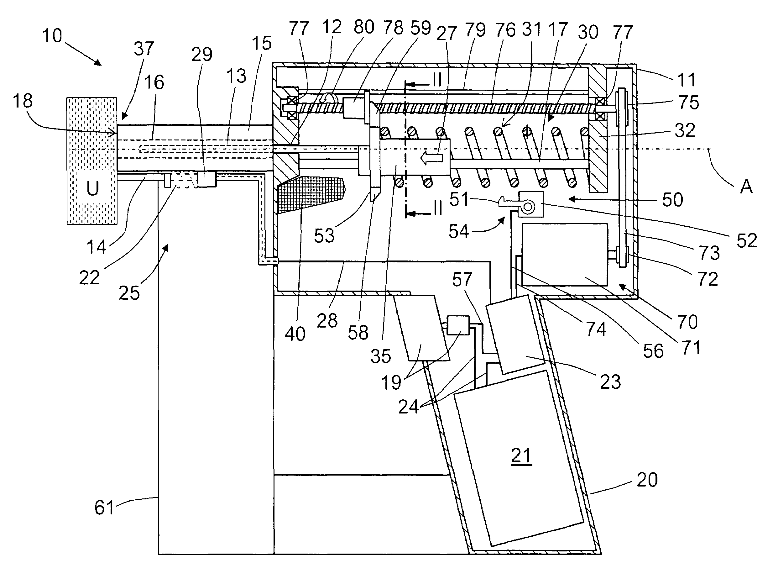
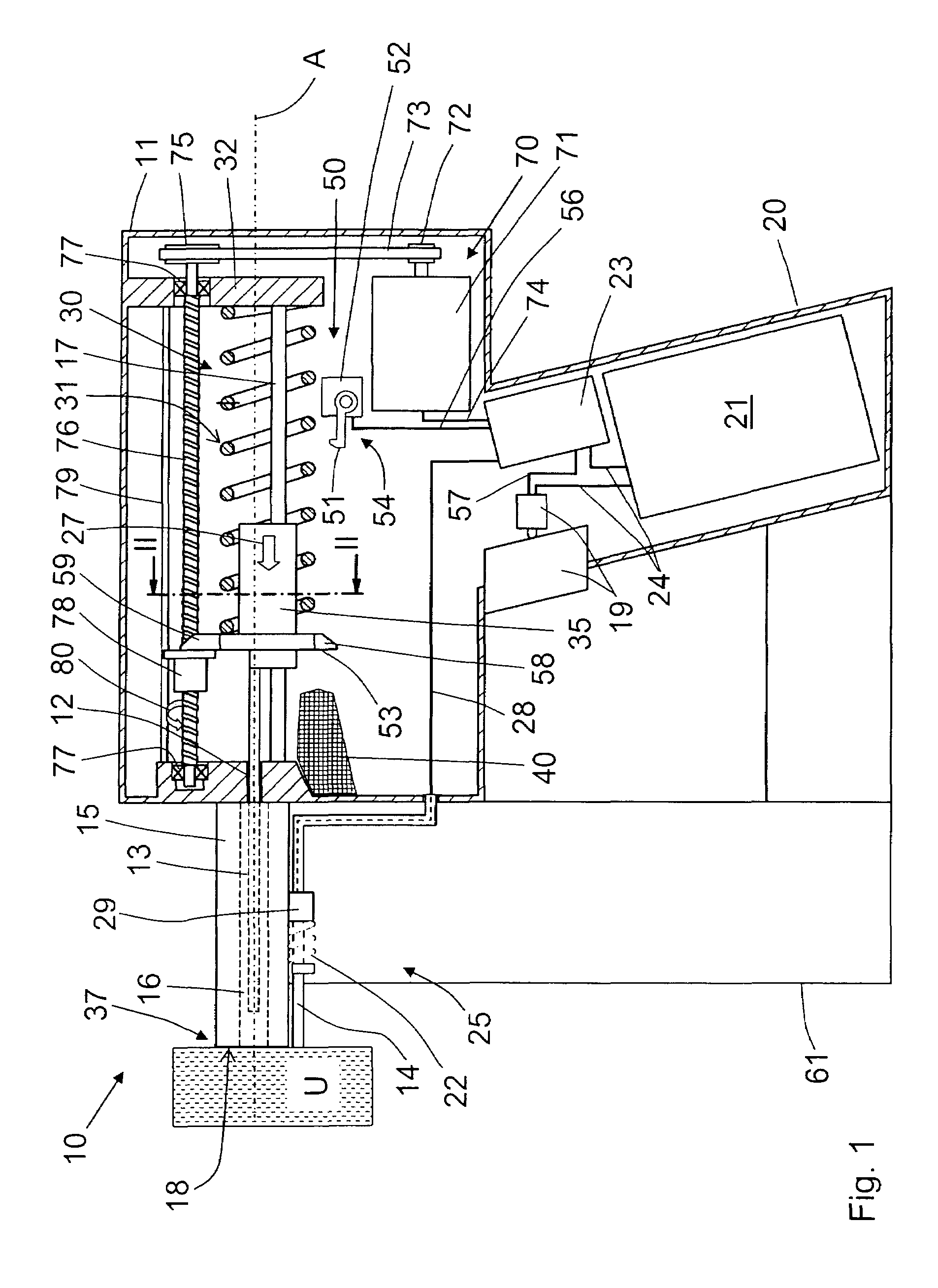
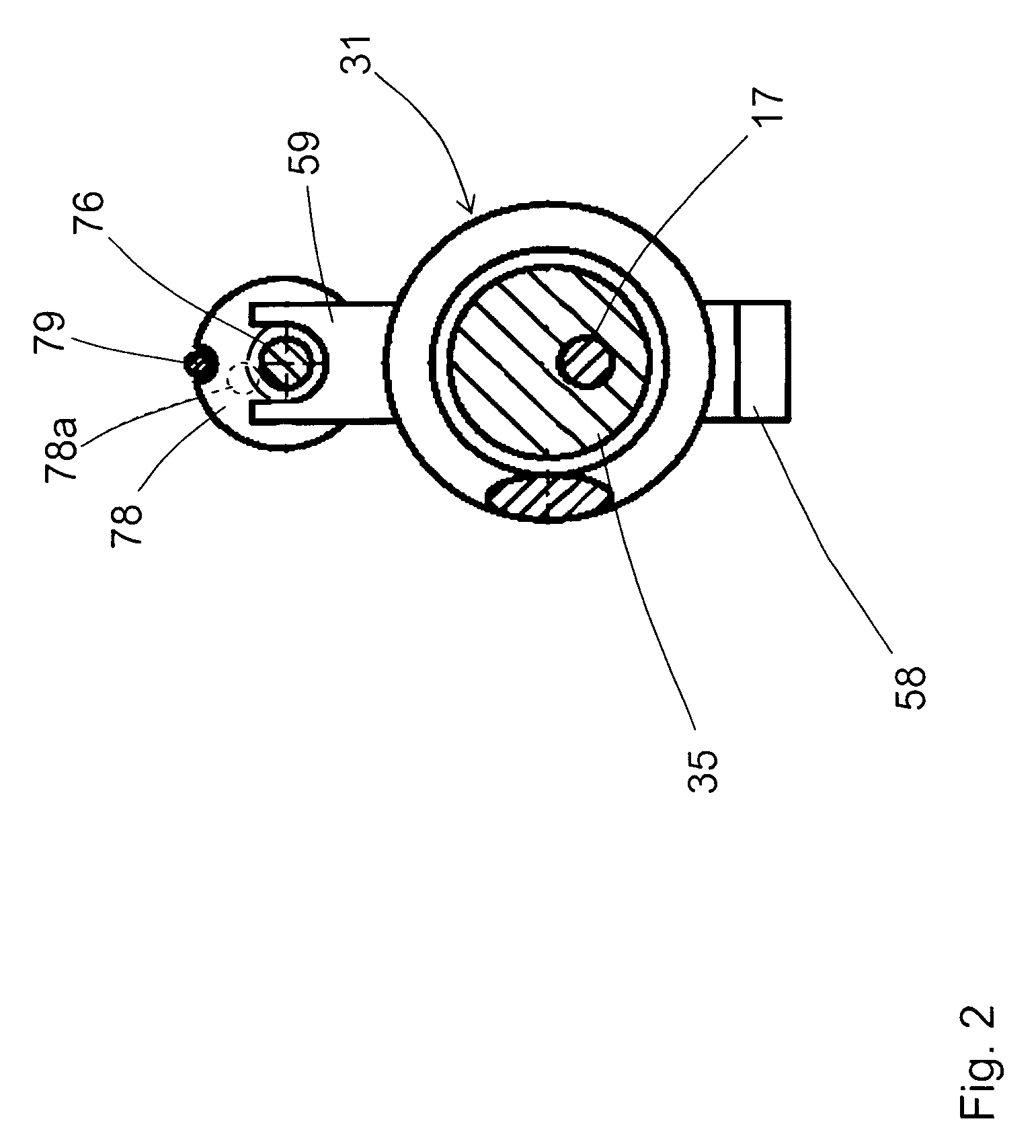
[0022]A hand-held power drive-in tool 10 according to the present invention, which is shown in FIGS. 1-4, is electrically operated and includes a housing 11 in which a drive for a drive-in ram 13 that generally designated with a reference numeral 30, is located. The drive-in ram 13 is displaceable in a guide 12, likewise located in the housing 11, and has a guide section 35 that is displaceable along a first guide member 17 (see in particular FIG. 2). The drive 30 includes a driving spring 31 that is supported with one of its opposite ends against the housing 11 at a stop surface 32, and is supported with the other of the opposite ends against the drive-in ram 13.

[0023]A muzzle part 15 adjoins an end of the guide 12 that faces in the drive-in direction 27. The muzzle part 15 has a drive-in channel 16 for a fastening element 60 and which extends coaxially with the guide 12. Sidewise of the muzzle part 15, there is arranged a magazine 61 for fastening elements in which the fastening e...


PUM

PropertyMeasurementUnit
displacementaaaaaaaaaa
axial distanceaaaaaaaaaa
forceaaaaaaaaaa

Abstract

A hand-held drive-in tool for driving fastening elements (60) in a workpiece (U) includes a drive-in ram (13) displaceable in a guide (12), a spring (31) for driving the drive-in ram (13), a tensioning device (70) for loading the driving spring (31), a locking device (50) for retaining, in its locking position (54), the driving spring (31) in its loaded position thereof (33), and a sliding nut (78) supported on a threaded spindle (76), which is rotatable by the motor (71) of the tensioning device (70), without a possibility of rotation thereabout but with a possibility of an axial displacement therealong, the sliding nut (78) being axially displaceable, upon actuation of the motor (71) of the tensioning device (70) by a control unit (23) of the drive-in tool (10), from the first end position (83) to the second end position (84) for displacing the driving spring (31) into the loading position (33) of the driving spring (33), and being subsequently displaceable from its second end position (84) into the first end position (83) to provide for displacement of the driving spring (31) to its release position.

Description

BACKGROUND OF THE INVENTION[0001]1. Field of the Invention[0002]The present invention relates to a hand-held drive-in tool for driving fastening elements in a workpiece and including a housing, a guide located in the housing, a drive-in ram displaceable in the guide for driving in a fastening element, a spring for driving the drive-in ram, a tensioning device for loading the driving spring and including a motor and a threaded spindle rotatable by the motor, a locking device for retaining, in its locking position, the driving spring in its loaded position, and an actuation switch for displacing the locking device from the locking position of the locking device to a release position of the locking device in which the driving spring is displaced from its loaded position to its release position for driving the drive-in ram.[0003]2. Description of the Prior Art[0004]Drive-in tools of the type discussed above can be driven, e.g., electrically, with a driving spring serving as an energy ac...

Claims


Application Information

Patent Timeline
Patent Type & Authority Patents(United States)
IPC IPC(8): B65C5/06
CPCB25C1/06B25C5/15
Inventor BLESSING, MATTHIASGSCHWEND, HANSSCHIESTL, ULRICHSPASOV, ROBERT
Owner HILTI AG
Why Eureka
Try Eureka