

Combined washer dryer
a combined washer and dryer technology, applied in drying machines, washing machines with receptacles, lighting and heating apparatus, etc., can solve the problems of catching fire, affecting the drying ability of clothes, and affecting the drying effect of clothes, so as to improve the drying ability, reduce the risk of burning clothes, and increase the drying capacity.
- Summary
- Abstract
- Description
- Claims
- Application Information
AI Technical Summary
Benefits of technology
Problems solved by technology
Method used
Image

Examples
example 1
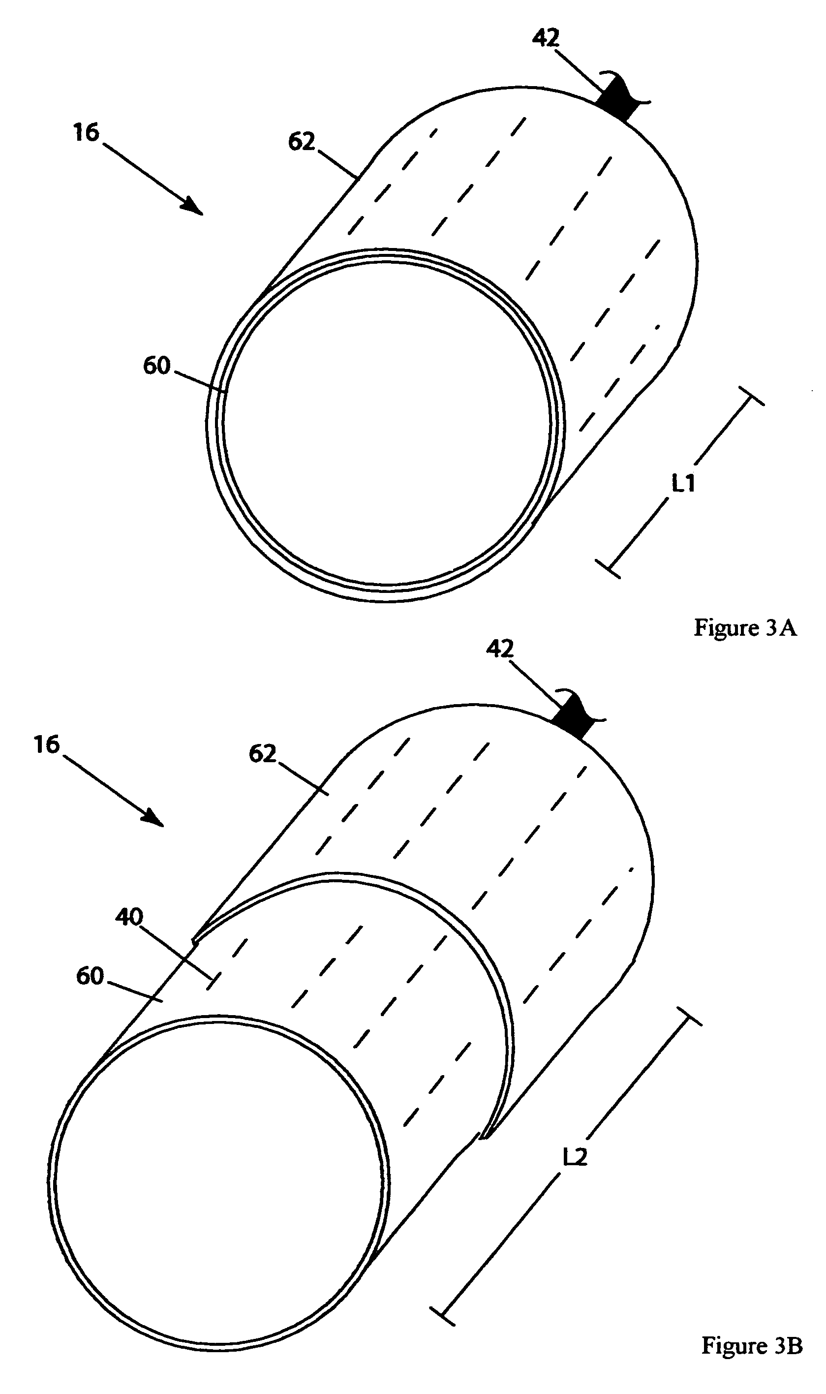
[0050]FIGS. 3A, 3B, 4A and 4B show a cylindrical drum 16 having a variable length. Referring to FIGS. 3A and 4A the drum 16 has a first length L1, and referring to FIGS. 3B and 4B the drum 16 has a second larger length L2. The length of the drum 16 can be varied by adapting the drum 16 from the L1 retracted position configuration to the L2 extended position configuration, and vice-versa. Of course, the drum 16 size can also be varied to many other lengths by adapting the drum 16 from positions other than L1 to positions other than L2. Some exemplary suitable ways of achieving this lengthwise adaptation are provided below.
[0051]One way to achieve this lengthwise variation is by configuring a first portion 60 of the drum 16 to be coaxially overlapped by a second portion 62 of the drum 16 (or vice-versa), providing an overlapping region 64. As illustrated, the diameter of the first portion 60 is slightly smaller (e.g. about 0.1-1 inch) than the second portion 62, although a larger or s...
example 2
[0056]FIGS. 7A and 7B show a cylindrical drum 16 having a moveable wall 82 disposed between the front and rear ends 26, 28 of the drum 16. The moveable wall 82 is advantageously linearly guided by a guidance mechanism 84 and urged by an actuating force 86 to provide a variable length drum 16. Referring to FIG. 7A the drum has a first length L1, and referring to FIG. 7B the drum has a second larger length L2. The length of the drum can be varied by adapting the drum 16 from the L1 retracted position configuration to the L2 extended position configuration, or vice-versa. Of course, the drum 16 size can also be varied to many other lengths by adapting the drum 16 from positions other than L1 to positions other than L2. Some exemplary suitable ways of achieving this variable length are provided below.
[0057]One way to achieve this variable length is by configuring the guidance mechanism 84 as comprising a fixed guide 88 that is operatively associated with a moveable member 90. The fixed ...
example 3
[0065]FIGS. 12A and 12B show a cylindrical drum 16 having a variable diameter. Referring to FIG. 12A the drum 16 has a first diameter D1, and referring to FIG. 12B the drum has a second larger diameter D2. The diameter of the drum 16 can be varied by adapting the drum from the D1 retracted position configuration to the D2 extended position configuration, or vice-versa. Of course, the drum 16 size can also be varied to many other diameters by adapting the drum 16 from positions other than D1 to positions other than D2. Some exemplary suitable ways of achieving this diameterwise adaptation are provided below.
[0066]Like with Examples 1 and 2, there are many ways to achieve this diameterwise adaptation. For example, one way is by configuring a first region of the drum 16 to overlap a second region of the drum 16, thereby producing a diameterwise overlapping portion. Another way to achieve this diameterwise adaptation is by configuring the drum 16 as a unitary member with at least one re...
PUM
 Abstract
Description
Claims
Application Information