
System and method for controlling heat exchanger fans

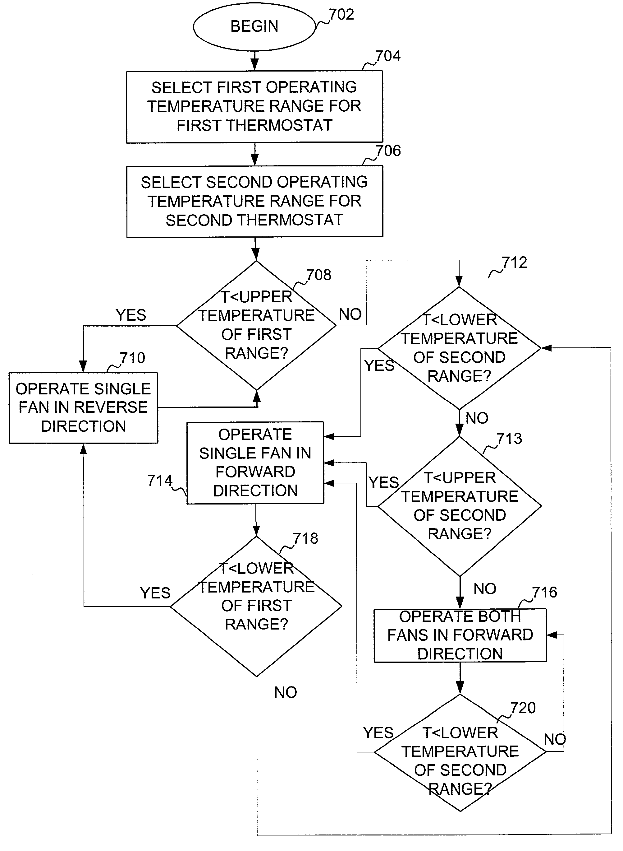
a technology of heat exchanger and fan controller, which is applied in the field of cooling system for battery and electronic component enclosures, can solve the problems of accumulated dirt and other debris that found its way into the cabinet through the protective mesh, and is likely to be blown out of the cabinet, so as to reduce the duration, reduce the operating time, and ensure adequate cooling

Inactive Publication Date: 2009-04-21
BELLSOUTH INTPROP COR
View PDF4 Cites 11 Cited by
  • Summary
  • Abstract
  • Description
  • Claims
  • Application Information

AI Technical Summary

Benefits of technology

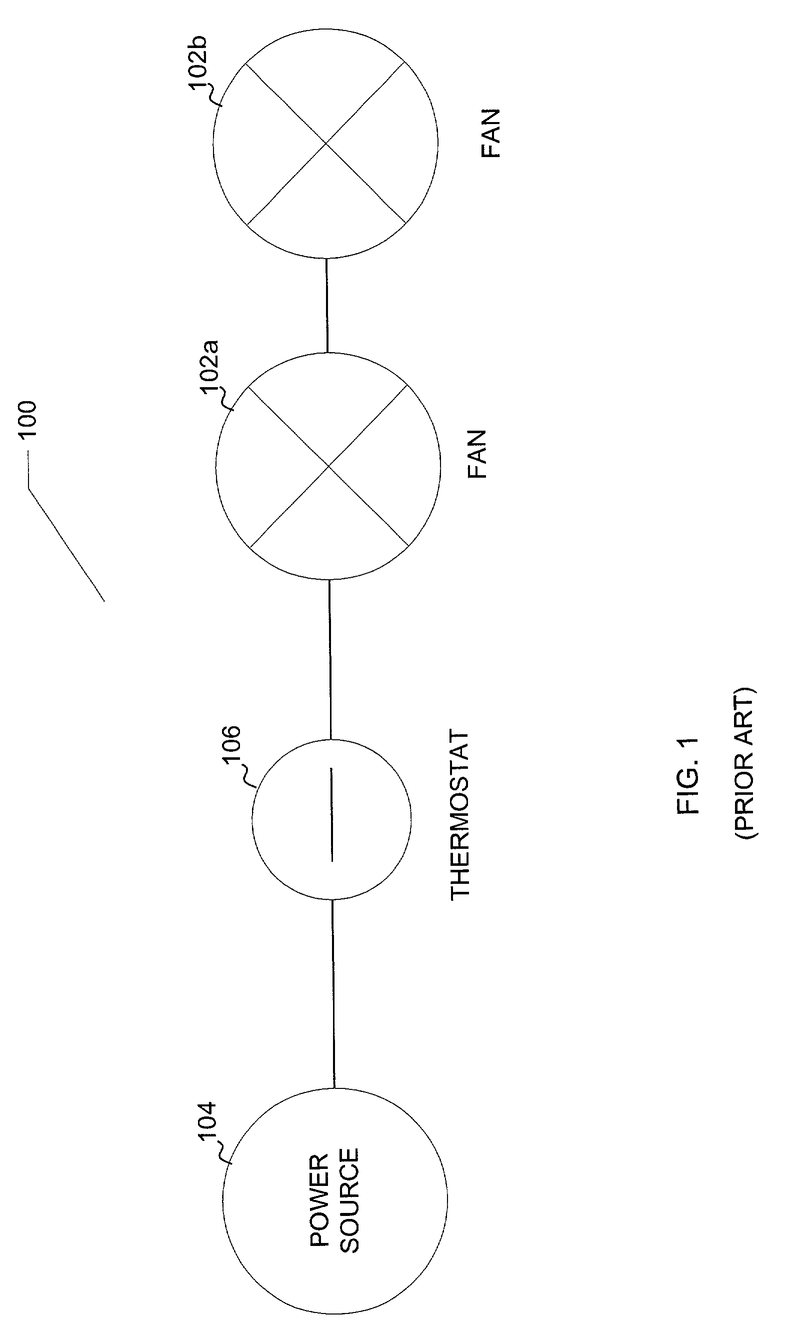
[0012]The present invention solves the forgoing problems with conventional heat exchanger fan controllers by providing a fan controller that reduces the duration for which fans comprising a heat exchange system are operating while still maintaining adequate cooling. Reducing the operating time in the manner indicated by the present invention provides multiple benefits. For example, the reduction in operating time increases the mechanical life of the fans since they are not operated as much as in conventional systems.
[0013]In addition, the present invention provides circuitry to reverse the operation of a fan for limited times to help reduce or eliminate clogging of the mesh that protects the intake for airflow to provide cooling to the cabinet. Reversing the fan allows the fan to blow air out of the cabinet to loosen and remove material that may have clogged the mesh during other operating times. Reversing the fan also tends to clean the cabinet enclosure. That is, any accumulated dirt and other debris that found its way into the cabinet through the protective mesh is likely to be blown out of the cabinet by the air being forced out of the cabinet due to the reverse operation of the fan.

Problems solved by technology

That is, any accumulated dirt and other debris that found its way into the cabinet through the protective mesh is likely to be blown out of the cabinet by the air being forced out of the cabinet due to the reverse operation of the fan.

Method used


Image

  • System and method for controlling heat exchanger fans
  • System and method for controlling heat exchanger fans
  • System and method for controlling heat exchanger fans

Examples


Embodiment Construction

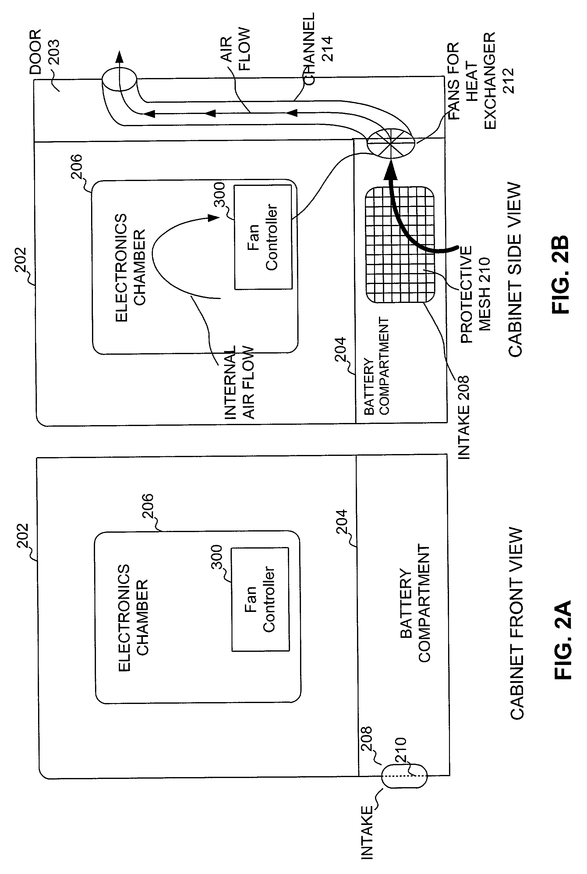
[0031]FIG. 2A is a schematic diagram of a front view of a cabinet 202 that can be used to house a electronic components and power supply. A battery compartment 204 houses a power supply such as a battery. The electronic components are located in an electronics chamber 206 of the cabinet. An intake 208 allows airflow through the cabinet to provide cooling for the battery and electronic equipment located in an electronics chamber. Intake 208 is also referred to as a vent or an air intake herein. Generally, intake 208 is located about 4 inches from the bottom of cabinet 202. A protective mesh 210 covers the vent primarily to prevent rodents and other small animals from crawling into the cabinet.

[0032]FIG. 2B is a schematic diagram of a side view of a cabinet that can be used to house electronics for telephone lines. As can be seen, cabinet 202 has an access door 203. Access door 203 allows service personnel to access the interior of cabinet 202 to maintain electronics, replace the batt...


PUM


Abstract

A fan controller reduces the percentage of time that fans used in a heat exchanger of an outdoor cabinet that houses electronics and power source must operate to provide required cooling to the electronics and power source. The fan controller can also reverse operation of a fan of the heat controller to help reduce clogging of air intakes as well as to clean the interior of the cabinet. In an embodiment, the controller operates the fans in the heat exchanger according to operating temperature ranges. Thermostats can be used to provide the operating temperature ranges. Depending on the state of the thermostats and the ambient temperature, the fan controller causes one fan to operate in the reverse direction while the other fan is idle, causes one fan to operate in the forward direction while the other fan is idle, or causes both fans to operate in the forward direction.

Description

[0001]This application claims the benefit of U.S. Provisional Application No. 60 / 348,121, filed Jan. 15, 2002, which is herein incorporated by reference in its entirety.BACKGROUND[0002]1. Field of the Invention[0003]The present invention relates generally to cooling systems for battery and electronic component enclosures. More specifically, the present invention relates to a fan controller for a fan-based heat exchanger for use in outdoor cabinets that house electronic components such as telephone digital loop carrier equipment and data and video transport equipment.[0004]2. Background of the Invention[0005]Telephone companies typically deploy outdoor cabinets to house electronic telephone equipment such as ADSL multiplexors. The cabinets typically have two chambers. One chamber houses the electronics. The second chamber houses a power source such as a battery. An exemplary cabinet is the Lucent 52B cabinet.[0006]The outdoor cabinets typically include a fan-based heat exchanger to p...

Claims


Application Information

Patent Timeline
Patent Type & Authority Patents(United States)
IPC IPC(8): F24F7/00F25D17/00
CPCH05K7/206H05K7/207F24F11/0079Y02B30/746F24F11/77Y02B30/70
Inventor HALL, CURTIS W.MENASCO, JR., HEYWARD E.
Owner BELLSOUTH INTPROP COR
Learn More