Static mixer

a microfluidic and mixer technology, applied in the direction of mixing, mechanical equipment, transportation and packaging, etc., can solve the problems of reducing the effectiveness of hydraulic action, clogging of small single holes, and affecting etc., to enhance the mixing effect of microfluids, inhibit abrupt pressure drop, and effectively

Inactive Publication Date: 2009-04-21
AEROMED TECH
View PDF8 Cites 26 Cited by
  • Summary
  • Abstract
  • Description
  • Claims
  • Application Information

AI Technical Summary

Benefits of technology

[0015]Advantageously, the novel multi-stage restrictor inhibits abrupt pressure drops. The novel pressure spike attenuator

Problems solved by technology

Although technically possible, practically such small single holes become clogged easily by contamination.
Either way, babbles may release into fluid channels causing hydraulic action to become “spongy,” i.e., to have lessened hydraulic effectiveness.
Accordingly, air mixed i

Method used


Image

  • Static mixer
  • Static mixer
  • Static mixer

Examples


Embodiment Construction

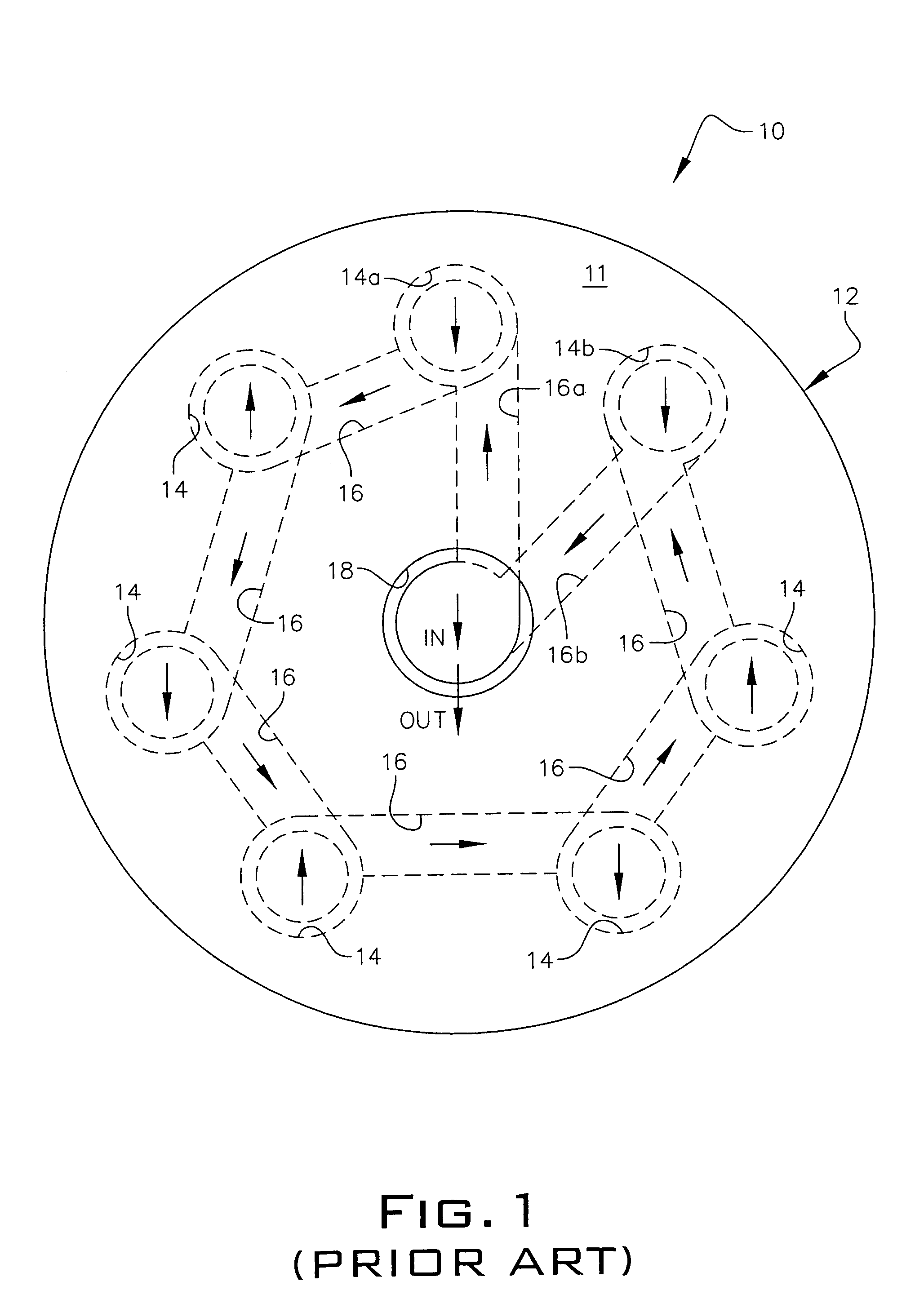
[0033]Referring now to FIG. 1, it will there be seen that a prior art micro-fluidic flow control device 10 includes multiple flow chambers 12 in stacked relation to one another. Each flow chamber is formed on a circular wafer or plate 11. Each flow chamber 12 includes a pair of circular lobes, collectively denoted 14, interconnected by an elongate, narrow rectangular channel, collectively denoted 16. Each channel 16 is straight so that each set of contiguous circular lobes 14 is formed by a pair of circular lobes that are disposed one hundred eighty degrees (180°) apart. Parallel rectangular channel lines tangentially connect one hundred eighty degree-opposed circular lobes, i.e., circular lobes 14 are circumferentially spaced apart from one another about the periphery of wafer 10 and are disposed in surrounding relation to central opening 18. Each channel 16 has a width common to that of the other channels and all channels are of uniform width along their respective extents.

[0034]M...


PUM


Abstract

A multi-stage restrictor includes an inlet plate, plates also being known as circular wafers, having a central non-restrictive aperture, a top fluid manipulation plate, an inter link plate, a bottom fluid manipulation plate and an exit plate disposed in stacked relation. An elongate channel interconnects pairs of circular lobes in the top and bottom fluid manipulation plates. In a multi-stage restrictor, a taper between five to ten degrees is formed in each of the channels of the top and bottom fluid manipulation plates. In a pressure spike attenuator, the taper is about fifteen to thirty degrees. In a static mixer, chevron-shaped protuberances are added to the tapered channels, one protuberance on each side of the each channel and each channel has a protuberance at its opposite end.

Description

BACKGROUND OF THE INVENTION[0001]1. Field of the Invention[0002]This invention relates, generally, to micro-fluidic control. More particularly, it relates to means for controlling flow in ultra low flow regimes involving small passages.[0003]2. Description of the Prior Art[0004]Conventional machining methods can make a flow passage having a diameter of 0.001 inch. Although technically possible, practically such small single holes become clogged easily by contamination.[0005]One known technique is to provide a series of nested large passages to create the effect of a single, much smaller hole. More particularly, a series of flow chambers is patterned into a circular wafer form, also called a plate. Each flow chamber includes two opposing circular lobes connected by a long, narrow rectangular channel. This technique has utility in hydraulic systems where very low flow passages that are not contamination sensitive are required.[0006]This prior art design employs parallel rectangular ch...

Claims


Application Information

Patent Timeline
IPC IPC(8): B01F5/06
CPCB01F5/0604B01F13/0059B01F25/422B01F33/30
Inventor LAWSON, JAY R.
Owner AEROMED TECH
Why Eureka
Try Eureka