Rugged design for hand held mobile terminals

a mobile terminal and bending technology, applied in the direction of telephone set construction, interconnection arrangements, support structure mounting, etc., can solve the problems of reducing the volumetric efficiency of the housing, reducing manufacturing time and labor costs. , to achieve the effect of reducing the need for bosses and/or fastening hardware, reducing labor costs, and improving torsional rigidity

Active Publication Date: 2009-04-21
SYMBOL TECH LLC
View PDF35 Cites 47 Cited by
  • Summary
  • Abstract
  • Description
  • Claims
  • Application Information

AI Technical Summary

Benefits of technology

[0008]The present invention provides systems and methods for a rugged hand held mobile terminal design. The mobile terminal includes a monocoque enclosure and a rail system provided within the monocoque enclosure. The rail system has electronic components for operation of the mobile terminal mounted thereon. Since the monocoque enclosure is a substantially one-piece cavity, the need for bosses and / or fastening hardware is mitigated. The mobile terminal also includes a display and display bezel. The display bezel includes at least one latch mechanism which corresponds with at least one notch and / or aperture formed in the rail system. Accordingly, the display bezel and rail system effectively exert a downward force on a gasket positioned around the display, which forms an environmental seal. Compressive loads are transferred to a top surface of the monocoque enclosure. The rail system can be further secured to the enclosure via a fastening mechanism (e.g., screw). The present invention provides several advantages over the conventional mobile terminal housing, such as: better torsional rigidity, simplified assembly, improved volumetric efficiency, reduced need for shock absorbing materials, lighter overall weight, decoupling of impact loads, and mitigation of stress concentrations.

Problems solved by technology

As mobile terminals become more and more powerful, a need for strength in the housing is at odds with a need to minimize volume occupied by the housing, and thus unavailable for packaging the electronics.
Thus, the existence of bosses 130 reduces volumetric efficiency of the housing 100.
Such assembly steps are generally time consuming and expensive in manufacturing.
Further, the conventional housing assembly has poor torsional rigidity due to discontinuity of the housing surfaces at the mating band.
Housing failure is often attributed to boss failure caused by deflection and impact load stresses.

Method used


Image

  • Rugged design for hand held mobile terminals
  • Rugged design for hand held mobile terminals
  • Rugged design for hand held mobile terminals

Examples


Embodiment Construction

[0017]The present invention relates to systems and methods for a rugged hand held mobile terminal design. The present invention will now be described with reference to the drawings, wherein like reference numerals are used to refer to like elements throughout. It is to be appreciated that the various drawings are not drawn to scale from one figure to another nor inside a given figure, and in particular that the size of the components are arbitrarily drawn for facilitating the reading of the drawings. In the following description, for purposes of explanation, numerous specific details are set forth in order to provide a thorough understanding of the present invention. It may be evident, however, that the present invention may be practiced without these specific details. In other instances, well-known structures and devices are shown in block form in order to facilitate describing the present invention.

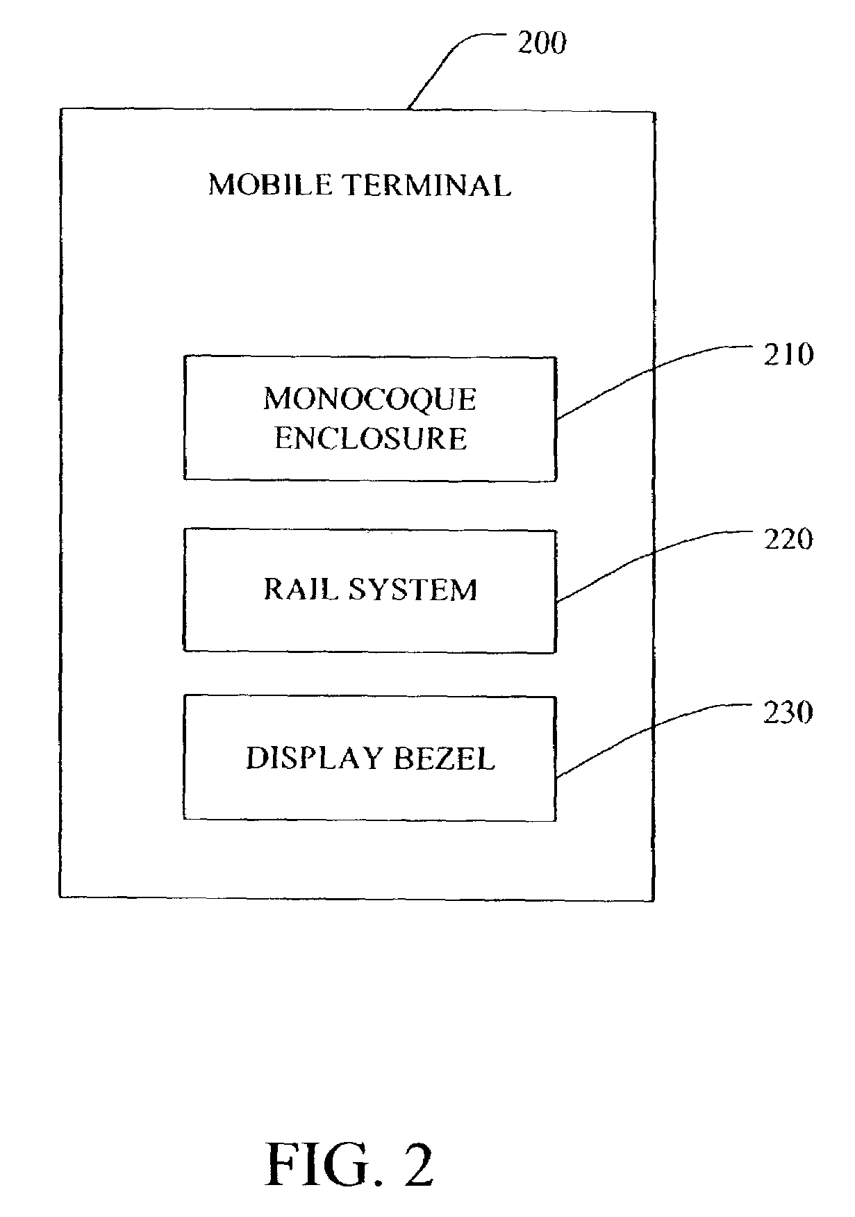
[0018]Referring initially to FIG. 2, a system 200 for a rugged hand held mobile ter...


PUM


Abstract

Systems and methods for a rugged hand held mobile terminal design are provided. The mobile terminal design includes a monocoque enclosure for housing electronic components. The electronic components are mounted on a rail system, which is positioned within an interior portion of the enclosure through an open end of the enclosure. The mobile terminal design also includes a display bezel. The display bezel and the rail system have mating parts for securing the assembly together.

Description

TECHNICAL FIELD[0001]The present invention generally relates to portable electronic devices. In particular, the present invention relates to systems and methods for a rugged design for hand held mobile terminals.BACKGROUND OF THE INVENTION[0002]Hand held mobile terminals, such as personal digital assistants (PDAs), have become widely accepted as personal and business organizational tools. Many users carry hand held mobile terminals on a daily basis. Accordingly, it is desired that housings for mobile terminals meet a number of criteria. A housing for a hand held mobile terminal should be aesthetically appealing. Moreover, the housing should be rugged to protect inner electronics from damage in the event of a drop. As mobile terminals become more and more powerful, a need for strength in the housing is at odds with a need to minimize volume occupied by the housing, and thus unavailable for packaging the electronics. Further, any latching mechanism used to hold the housing together sh...

Claims


Application Information

Patent Timeline
Patent Type & Authority Patents(United States)
IPC IPC(8): H04B1/38H04M1/02H04M1/18H04W88/02H05K7/14
CPCH04B1/3833H04M1/0249H04M1/0266H04M1/18H05K7/1418
Inventor WULFF, THOMASSPANO, ROBERT A.ILKHANOV, AZERMAIMAN, MITCHELL
Owner SYMBOL TECH LLC
Why Eureka
Try Eureka