Rotary shoe storage device

a shoe storage device and rotary technology, applied in the direction of show hangers, dismountable cabinets, cabinets, etc., can solve the problems of limiting the quantity of shoes stored, wasting closet space above shoes, wasting closet space or obstructed view of shoes stored on the lower shelf, etc., to achieve efficient use of storage space, facilitate visual identification of shoes, and facilitate manufacturing

Inactive Publication Date: 2009-04-28
ZIPETO KENNETH M +1
View PDF22 Cites 16 Cited by
  • Summary
  • Abstract
  • Description
  • Claims
  • Application Information

AI Technical Summary

Benefits of technology

[0013]A further object of the present invention is to provide a rotary shoe storage device which is economical to manufacture.
[0014]Yet a further object of the present invention is to provide a rotary shoe storage device which permits ease of visual identification of shoes.
[0015]An additional object of the present invention is to provide a rotary shoe storage device which allows efficient use of storage space.

Problems solved by technology

Placement of shoes directly on the floor limits the quantity of shoes stored in the closet, wastes the closet space above the shoes beneath the hanging clothing and necessitates undesirable bending in order to retrieve them.
Shelf-like shoe racks are typically limited in depth resulting in wasted closet space or obstructed view of shoes stored on the lower shelf.
Some people prefer to store the shoes beneath a conventional frame bed but are limited to placing shoes in a single row in order to easily locate and retrieve a desirable pair of shoes.
However, the disadvantages of such a shoe rack are in their fixed mounting, in complexity of the heel support and in wasted shelf space due to use of the bushing to govern heel placement in order to organize shoes.
The use of drawers prevents ease of visually locating a particular pair of shoes.
Such fixed compartment configuration limits the quantity and sizes of stored shoes.

Method used


Image

  • Rotary shoe storage device
  • Rotary shoe storage device

Examples


Embodiment Construction

[0020]Prior to proceeding to the more detailed description of the present invention, it should be noted that, for the sake of clarity and understanding, identical components which have identical functions have been identified with identical reference numerals throughout the several views illustrated in the drawing figures.

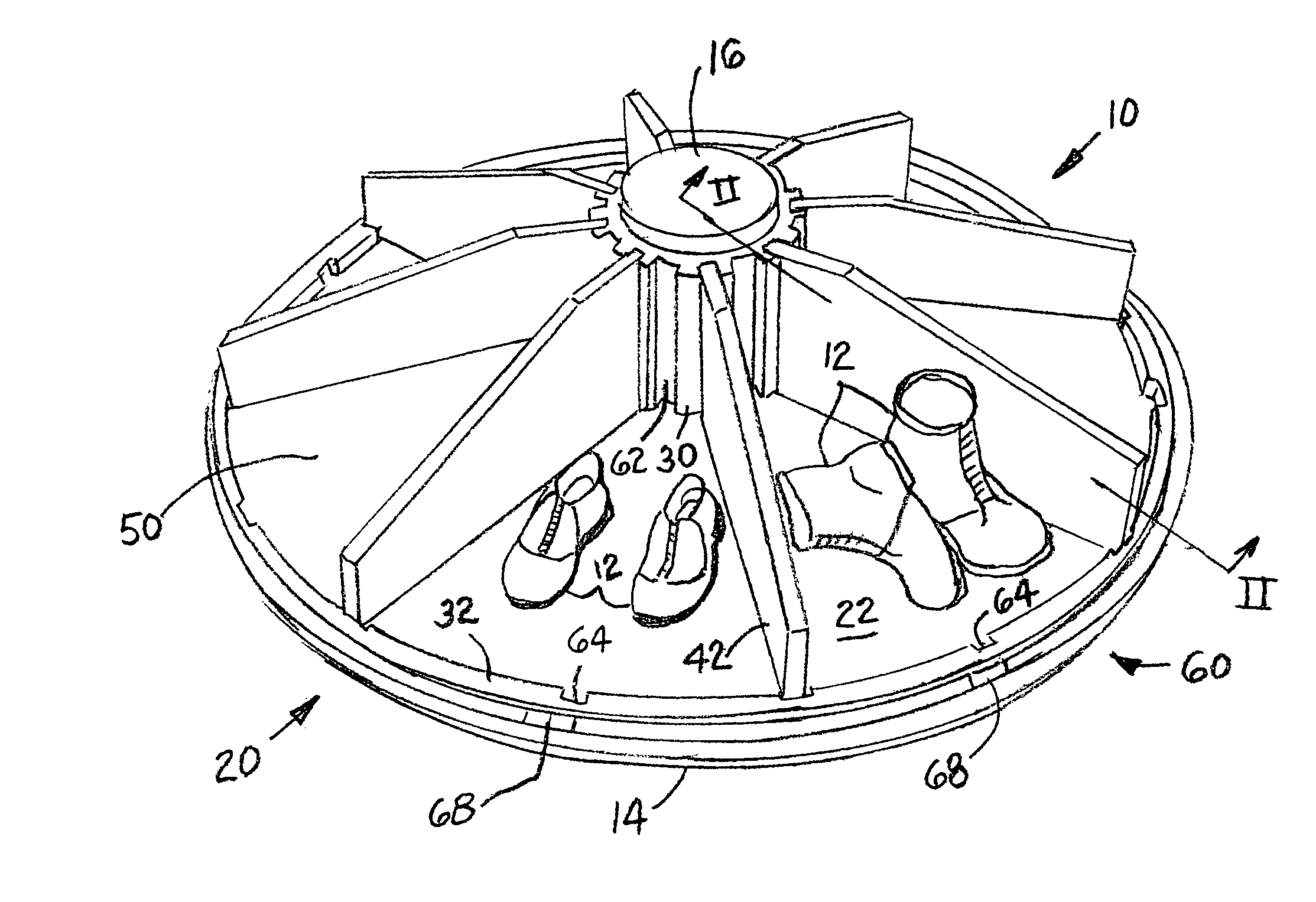
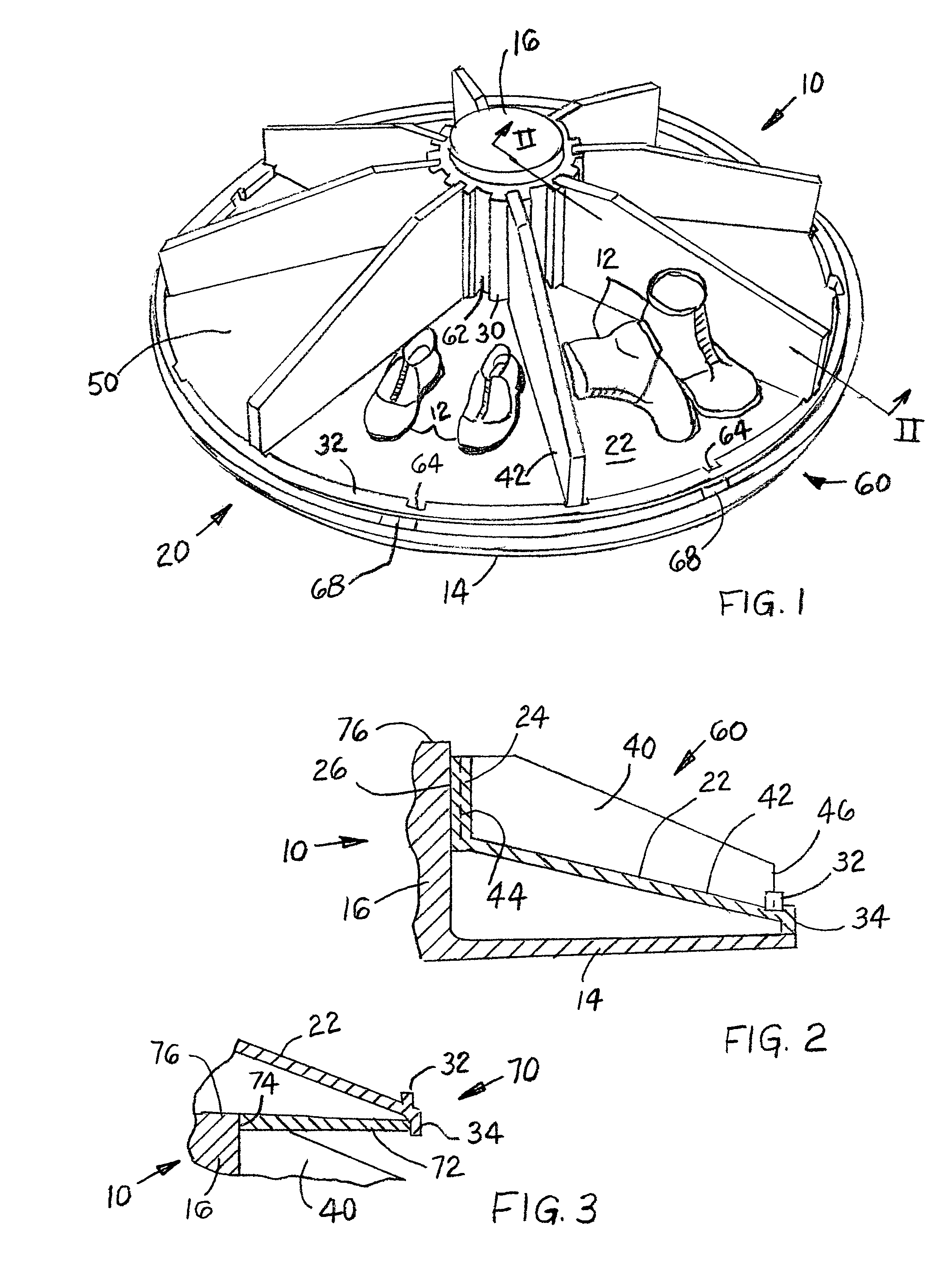
[0021]Reference is now made, to FIGS. 1-3, wherein there is shown a rotary device, generally designated 10, for storing shoes 12. Such rotary shoe storage device 10 includes a base means 14 having each of a predetermined size and a predetermined shape. A pivot means 16 extends outwardly from and is attached to the base means 14. Preferably, base means 14 and pivot means 16 are formed as an integral single piece unit. While a substantially planar configuration of the base means is illustrated, it will be understood that other configurations of such base means 14 may be applied for placing the rotary shoe storage device 10 onto a surface.

[0022]A shoe support means, g...


PUM


Abstract

A rotary shoe storage device includes a base member and a pivot extending outwardly from and attached to the base member. A shelf for supporting shoes has an inclined surface and a hub connected to and extending outwardly from the shelf. The hub is provided with an aperture for engaging the pivot thus enabling pivoting of the shelf about the base member. The hub is further provided with a plurality of surface slots for receiving partitions which divide the shelf into adjustable compartments to accommodate various shoe sizes. The shelf is provided with a peripheral flange to generally confine the shoes within each compartment. The device can be placed beneath a conventional bed or mounted to an underside of the bed. The shelf can be provided with a clamp for mounting to a vertically disposed shaft of a rotary shoe rack.

Description

FIELD OF THE INVENTION[0001]The present invention relates, in general, to a rotary tray or rack and, more particularly, this invention relates to a rotary tray or rack for storing shoes beneath a conventional frame bed or in a wardrobe closet.BACKGROUND OF THE INVENTION[0002]As is generally well known, shoes are commonly stored either directly on the floor of the wardrobe closet beneath hanging clothing and other household belongings or in shelf-like shoe racks which are generally placed along the rear wall of such wardrobe closet. Placement of shoes directly on the floor limits the quantity of shoes stored in the closet, wastes the closet space above the shoes beneath the hanging clothing and necessitates undesirable bending in order to retrieve them. Shelf-like shoe racks are typically limited in depth resulting in wasted closet space or obstructed view of shoes stored on the lower shelf.[0003]Some people prefer to store the shoes beneath a conventional frame bed but are limited t...

Claims


Application Information

Patent Timeline
Patent Type & Authority Patents(United States)
IPC IPC(8): A47G29/00
CPCA47B49/00A47B61/04
Inventor ZIPETO, KENNETH M.ZIPETO, JENNIFER S.
Owner ZIPETO KENNETH M
Why Eureka
Try Eureka