Train detection

a technology of detection mechanism and train, which is applied in the direction of railway signalling, railway components, transportation and packaging, etc., can solve the problem of too high resistance of the wheel to the rail interface to achieve activation

Inactive Publication Date: 2009-04-28
SIEMENS RAIL AUTOMATION HLDG
View PDF11 Cites 24 Cited by
  • Summary
  • Abstract
  • Description
  • Claims
  • Application Information

AI Technical Summary

Benefits of technology

[0007]It is an object of the present invention to provide a train detection mechanism wh

Problems solved by technology

Conditions of rail head contamination, or the light weight of some vehicles can resul

Method used


Image

  • Train detection
  • Train detection
  • Train detection

Examples


Embodiment Construction

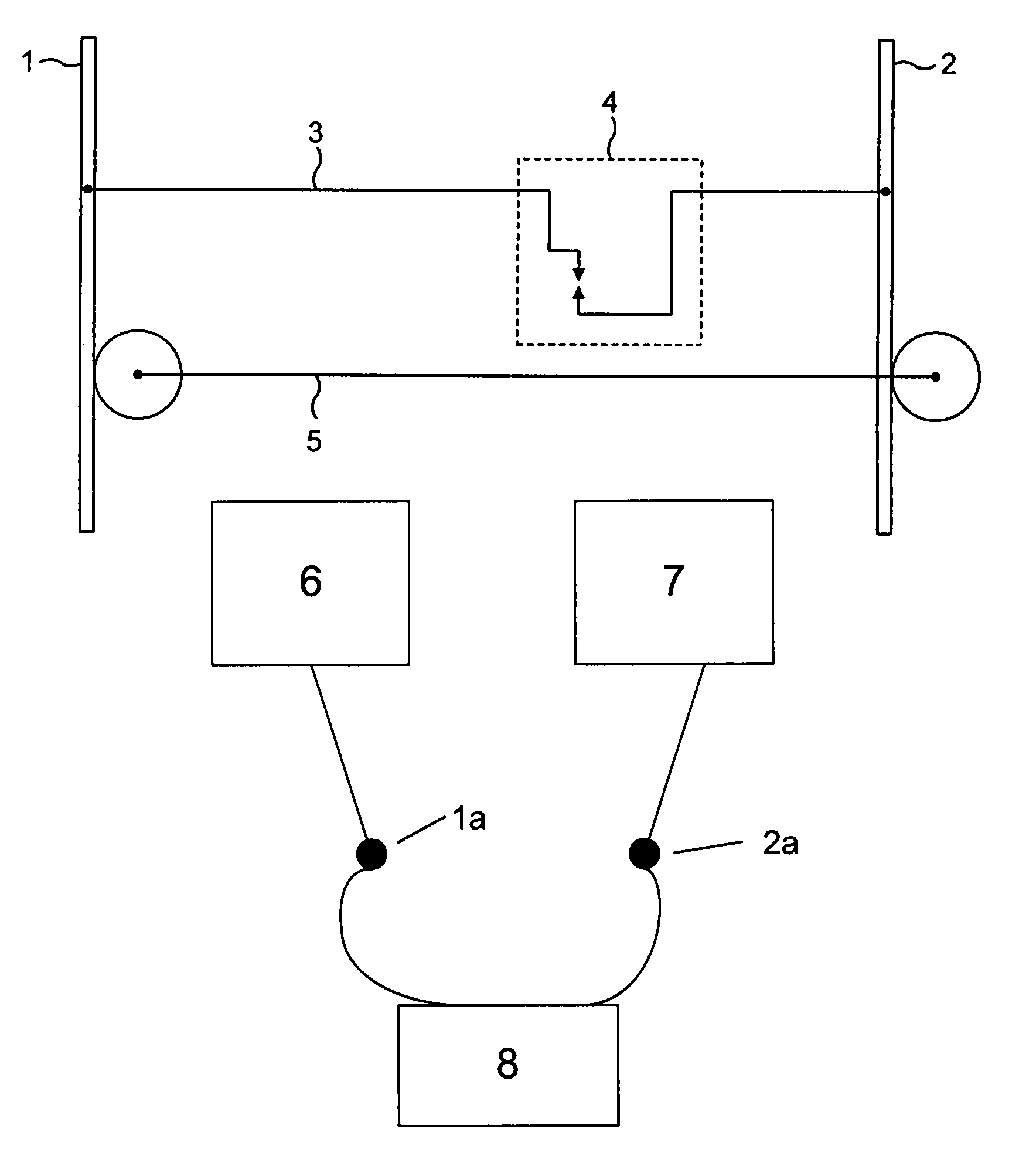
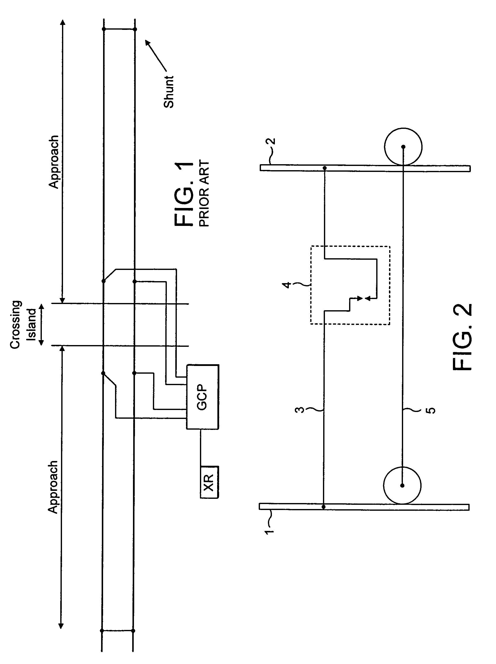
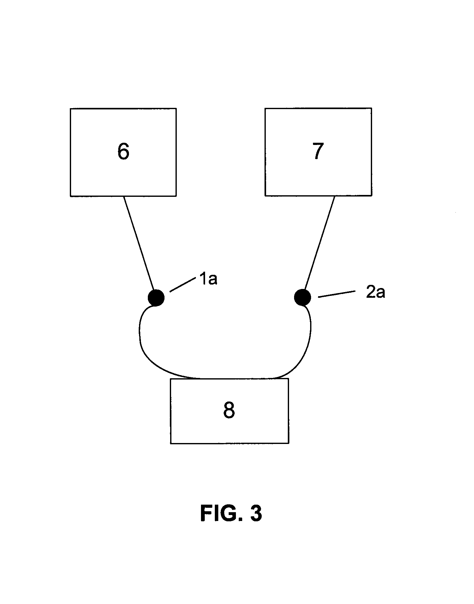
[0031]With reference now to FIG. 2, a shunt arrangement is shown for a train detection mechanism in accordance with the present invention, and to FIG. 3, which shows a relationship between various components including current injection means 6, current receiving means 7 and impedance measuring means 8, and the first ends 1a,2a of rails 1,2, respectively. FIG. 2 shows a portion of first and second rails 1 and 2 in the vicinity of the distal end of the track circuit from the current injection means 6. The rails 1, 2 are electrically connected by a termination shunt 3. In an advance on the prior art, the shunt 3 includes a switch 4, such as a treadle, connected in series with the shunt 3. The switch 4 is normally closed in its default state in the absence of the passage of the train. When the switch is closed, current can flow from the injection means, along rail 1, through shunt 3 and back along rail 2 to current receiving means 7. Of course, the current used will usually be a.c. and ...


PUM


Abstract

A train detection mechanism for detecting the presence of a train on a section of track, the track section including first and second rails 1, 2 and delimited by first and second ends thereof, includes current injector for injecting current into the first rail at the first end of the section and current receiver for receiving current from the second rail at the first end of the section, and a shunt 3 connected between the first and second rails at the second end of the section, characterized in that the shunt includes a switch 4 for controlling current flow through the shunt, the switch being operable by the passage of a train.

Description

CROSS-REFERENCE TO RELATED APPLICATION(S)[0001]This application claims the benefit of and incorporates by reference the entire disclosure of United Kingdom Application No. 0419995.6, filed Sep. 9, 2004 pursuant to 35 U.S.C. § 119(a-d).BACKGROUND OF THE INVENTION[0002]This invention concerns a train detection mechanism and method for detecting the presence of a train on a section of track.[0003]It is common to determine the presence of a train on a section of track by using a track circuit. Conventionally the track circuits may be arranged in two fundamental ways, those where the transmitter and receiver are located at different positions within the track circuit and those where the transmitter and receiver are co-incident at one end of the track circuit. With the co-incident method, current is injected into one of the rails. Normally, i.e. in the absence of a train, the current will flow along the rail, pass through a shunt provided to connect the rails and then return back along th...

Claims


Application Information

Patent Timeline
IPC IPC(8): B61L23/00B61LB61L1/18
CPCB61L1/18
Inventor FRANCIS, JONATHAN DAVIDROBERTSHAW, PAUL
Owner SIEMENS RAIL AUTOMATION HLDG
Why Eureka
Try Eureka