
High wind fence system

a high-wind fence and high-strength technology, applied in the field of fencing, can solve the problems of over-350 billion in damage, increased risk to life and property, and increased risk of life and property, and achieve the effect of reducing or eliminating the damage caused by the fen

Inactive Publication Date: 2009-04-28
GARRITY ROBERT M
View PDF6 Cites 24 Cited by
  • Summary
  • Abstract
  • Description
  • Claims
  • Application Information

AI Technical Summary

Benefits of technology

"The present invention is a fence system that includes panels that can be pivoted between a vertical and horizontal position. When in the horizontal position, the fence panels can protect the fence from high winds and wind-borne debris. The panels have hinged brackets that allow them to pivot between the two positions. The fence system also includes hold-down assemblies that prevent the panels from lifting during high wind situations. The objective of this invention is to provide a high wind fence system that can provide privacy and protect the fence from damage caused by high winds and wind-borne debris. The fence system can also be used to convert a pre-existing fence into a hurricane fence."

Problems solved by technology

Together, these disasters have caused in excess of $350 billion in damage.
Population growth along the coastline of the United States has resulted in an increased risk to life and property from hurricane related damage.
Homes, buildings, fences and other permanent structures often suffer substantial damage when windborne debris and storm generated winds overload the capacity of the structure.
These fences are often constructed of wood, plastic, aluminum, steel or other structural material at great expense to the homeowner.
Due to the permanent and structural nature of fences, they are often damaged or destroyed by the strong winds generated in coastal storms.
Removal and storage of the fence panels before a storm is generally impractical.
Most fences are not constructed to allow for disassembly without destroying the fence panels.
Even if the panels could be removed, storage of the panels would be difficult and would consume a significant portion of the available storage space.
In addition, the inherent weight of the fence panels would require a support structure to prevent the panels from tipping or falling while stored.
Most of these dwellings do not have a garage or other space which could be dedicated to fence panel storage.

Method used


Image

  • High wind fence system
  • High wind fence system
  • High wind fence system

Examples


Embodiment Construction

[0026]While the present invention is susceptible of embodiment in various forms, there is shown in the drawings and will hereinafter be described a presently preferred embodiment with the understanding that the present disclosure is to be considered an exemplification of the invention and is not intended to limit the invention to the specific embodiments illustrated.

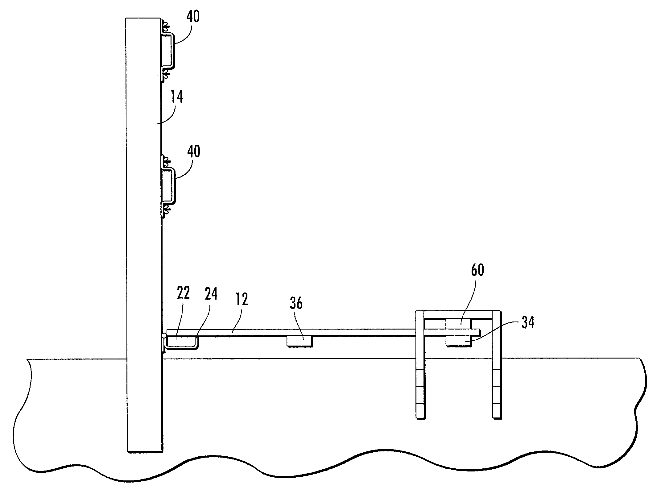
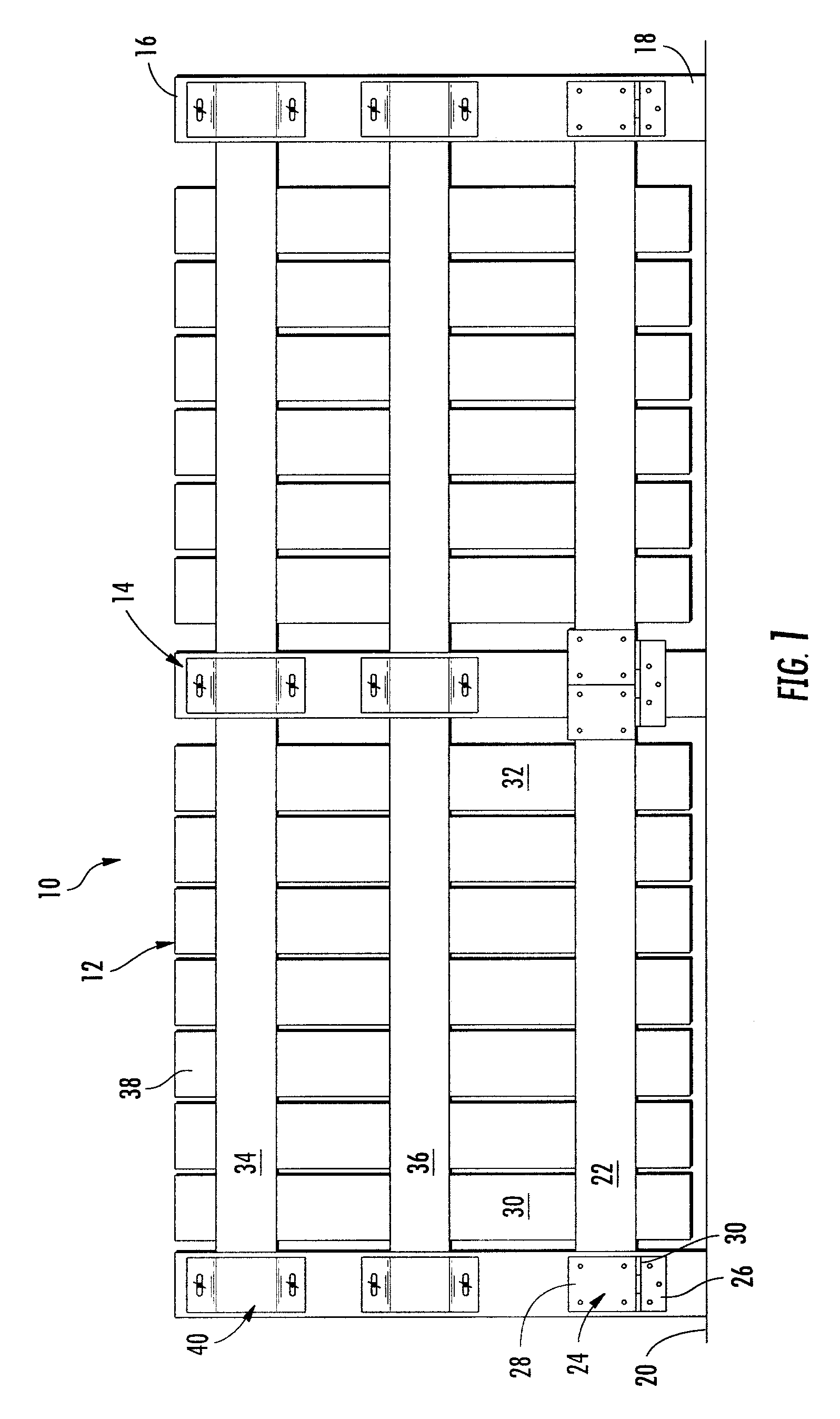
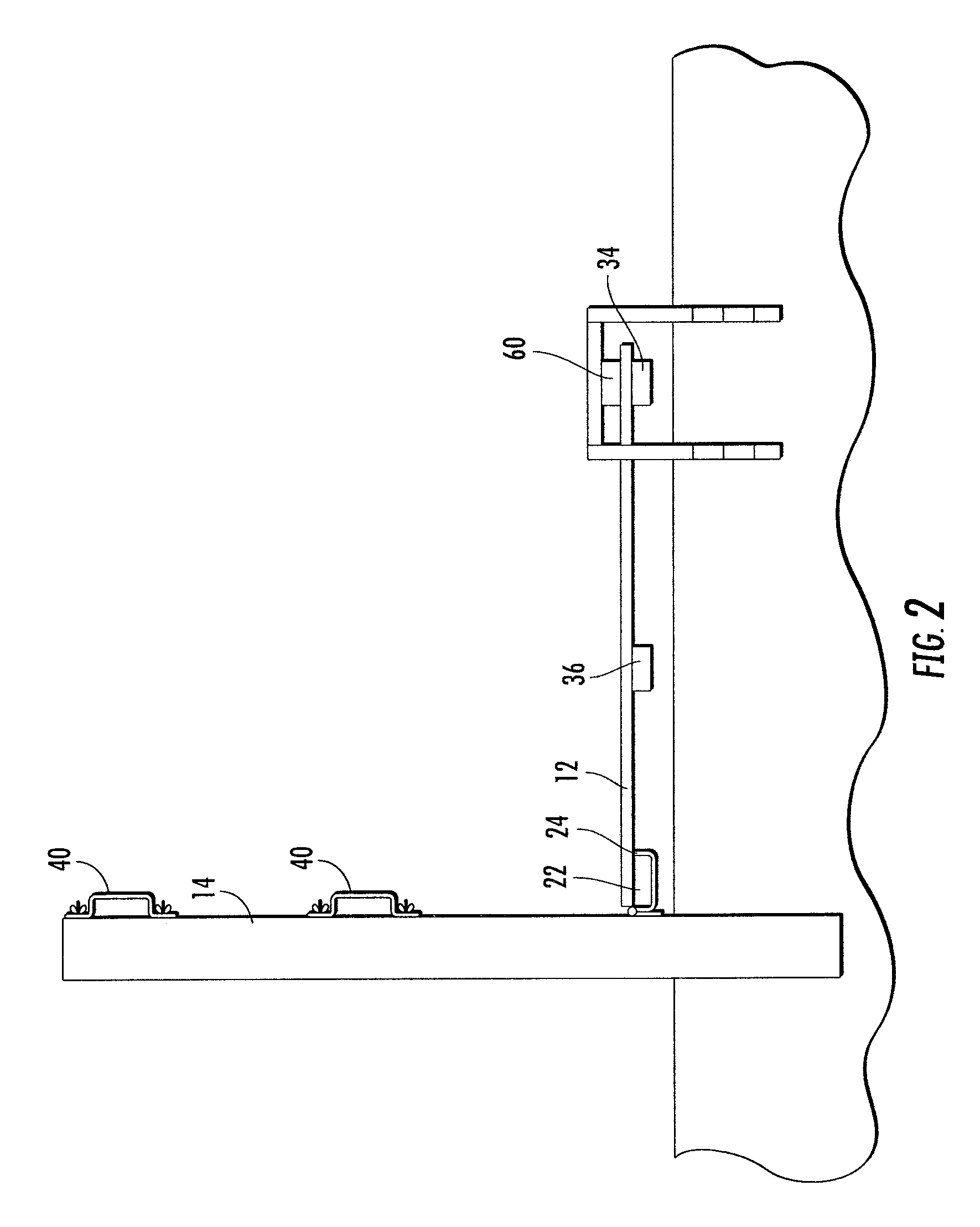
[0027]Referring to the FIGS. 1 and 2, a hurricane fence system 10 is illustrated. The hurricane fence system includes permanently mounted posts 14 and at least one panel 12 that is constructed and arranged to be pivoted between a vertical orientation for privacy and a horizontal orientation for storm protection. FIG. 1 illustrates a preferred embodiment of the fence system 10. The fence includes at least two spaced apart substantially vertical posts 14. The posts having an upper portion 16 and a lower portion 18, the lower portion is constructed and arranged to be secured to or within a ground surface 20. The lower porti...


PUM


Abstract

The present invention provides a fence system for homes, buildings and the like. The fence system according to the instant invention includes panels constructed and arranged to be pivoted between a vertical orientation and a horizontal orientation. When connected to permanently mounted posts in a vertical orientation, the fence panels may be utilized for privacy and / or security. Pivoting the panels to horizontal position during storms, such as hurricanes, reduces or eliminates the damage caused to the fence by high winds and / or wind-borne debris.

Description

FIELD OF THE INVENTION[0001]This invention relates generally to fencing. More specifically, to a fencing system that includes fence panels constructed and arranged to be pivoted to a horizontal position to prevent fencing damage from high winds and flying debris.PRIOR ART BACKGROUND[0002]The United States has experienced over 60 weather-related disasters in the past 25 years, each of which has caused in excess of $1 billion in damages. Together, these disasters have caused in excess of $350 billion in damage.[0003]Population growth along the coastline of the United States has resulted in an increased risk to life and property from hurricane related damage. There are approximately 153 million residents that live in coastal counties of the United States, with areas such as Texas, Florida, and the Carolinas, where hurricanes frequently strike, experiencing rapid population growth. In addition, many coastal areas experience substantial but temporary population increases from holiday, we...

Claims


Application Information

Patent Timeline
Patent Type & Authority Patents(United States)
IPC IPC(8): E04H17/14
CPCE04H17/16E04H2017/1491E04H2017/1495Y10S256/02E04H17/1445E04H17/1448E04H17/17
Inventor GARRITY, ROBERT M.
Owner GARRITY ROBERT M
Learn More