Conducting wire anti-drop structure

a technology of conducting wire and anti-drop, which is applied in the direction of incorrect coupling prevention, coupling device connection, engagement/disengagement of coupling parts, etc., can solve the problems of reducing the transmission quality of power or electronic signals, power failure, and loosening of connecting wires and sockets, so as to prevent the loosening of conducting wires, simple structure, and convenient installation

Inactive Publication Date: 2009-04-28
ZIPPY TECH
View PDF5 Cites 12 Cited by
  • Summary
  • Abstract
  • Description
  • Claims
  • Application Information

AI Technical Summary

Benefits of technology

[0005]The present invention is advantageous of simple structure, convenient installation and preventing the conducting wire from being loose owing to vibration or inappropriate pulling, so as to effectively avoid the damage caused as the conducting wire becomes loose.

Problems solved by technology

In the prior art, the connecting terminal of the conducting wire is simply plugged into the socket of the power supply without any fixing or buckling device, so that if a pulling force or an accidental pulling or vibration is applied to the connecting terminal, or the friction between the connecting terminal and the socket becomes insufficient after multiple times of plugging and pulling, the connection between the connecting wire and the socket might become loose and even come off, which actually might reduce the transmission quality of power or electronic signal or even cause power failure.
For electronic devices, such as computer or other precision instruments, instable power transmission or disconnection might cause data losing and also might damage the device itself.
However, the connection between power cords lacks an assistant mechanism to fix thereof, and thus, the connection between two power cords might easily become loose so as to cause instable power transmission and even damage the power supply and the electronic device.

Method used


Image

  • Conducting wire anti-drop structure
  • Conducting wire anti-drop structure
  • Conducting wire anti-drop structure

Examples


Embodiment Construction

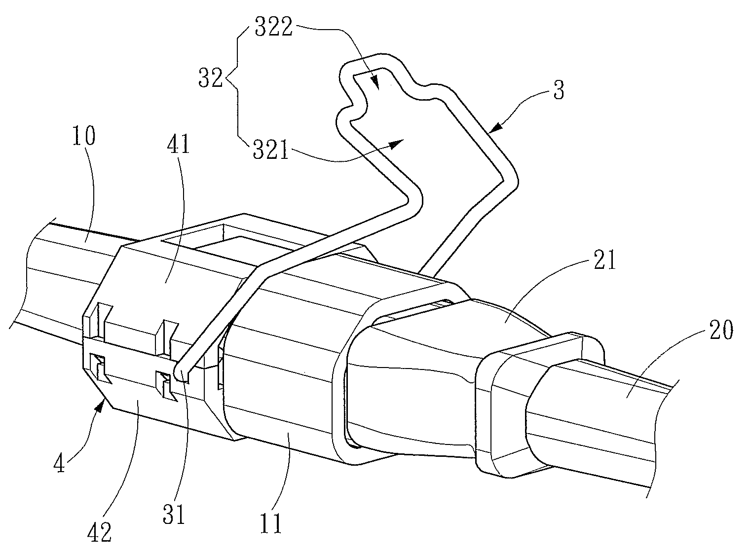
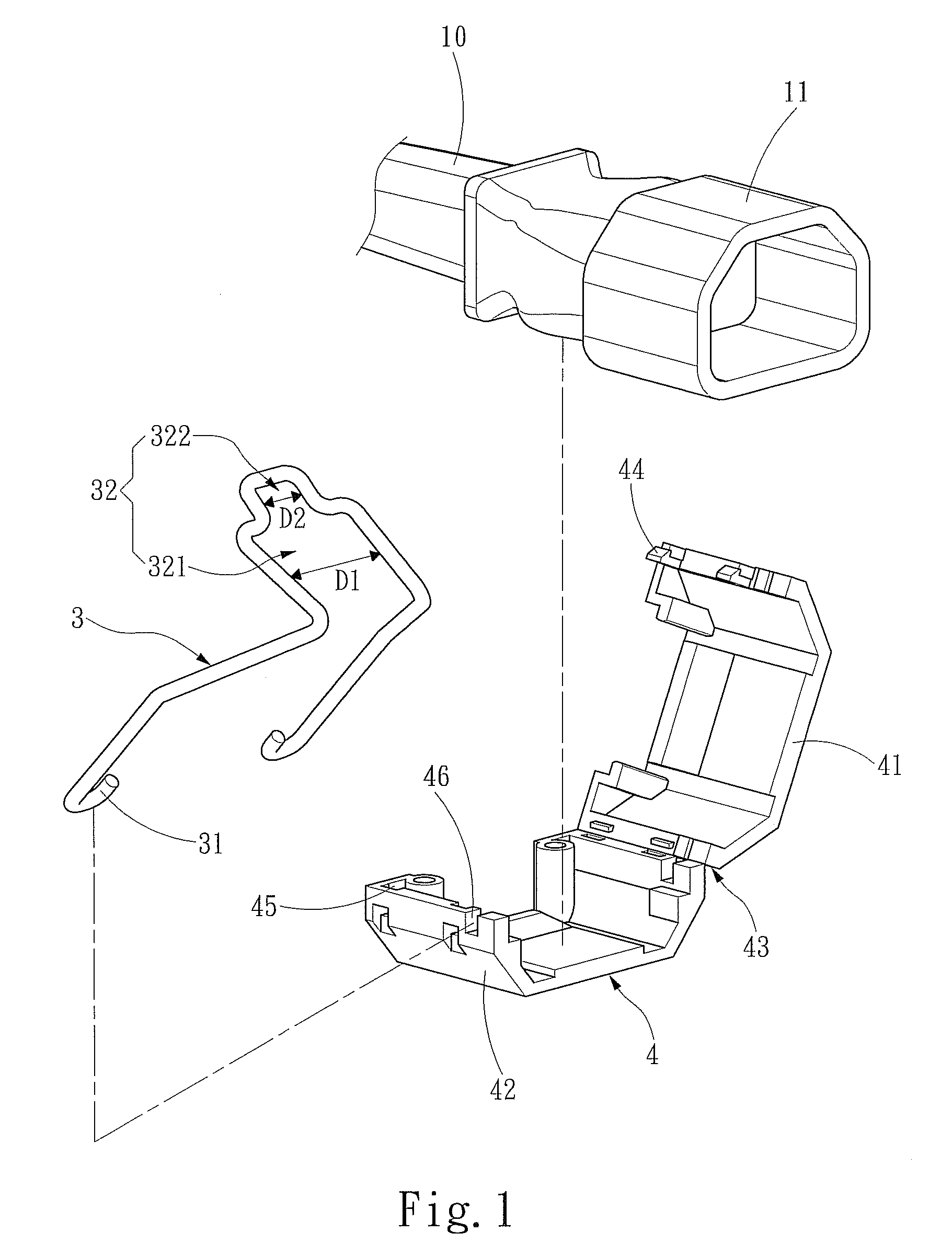
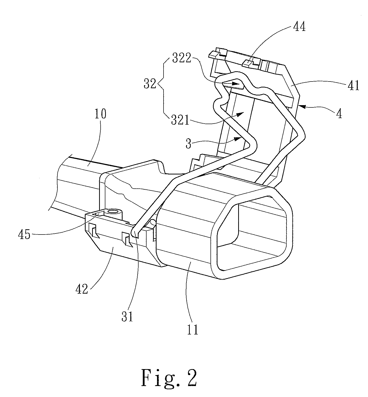
[0015]Please refer to FIG. 1, FIG. 2 and FIG. 3 which shows an embodiment of the present invention. The present invention is related to a conducting wire anti-drop structure for fixing two mutually connected conducting wires 10, 20 (as shown in FIG. 3), and the two conducting wires 10, 20 respectively have a connecting terminal 11, 21. The connecting terminal 11 is connected to a position-limiting device 3 through a positioning device 4, wherein the positioning device 4 includes an tipper housing 41 and a lower housing 42, and the upper and the lower housings 41, 42 are connected through a pivot portion 43. Moreover, the upper housing 41 and the lower housing 42 respectively have an integrating portion 44, 45 at the end opposite to the pivot portion 43, and the upper and the lower housings 41, 42, through the integrating portions 44, 45, are buckled together to form a ring shape for sleeving on the connecting terminal 11 of the conducting wire 10. Furthermore, the positioning device...


PUM


Abstract

The present invention is related to a conducting wire anti-drop structure for fixing two mutually connected conducting wires, which respectively have a connecting terminal for connecting with each other. The conducting wire anti-drop structure is characterized in that a positioning device is mounted on the connecting terminal of one of the conducting wires and has a positioning portion. The positioning portion is used to connect with a position-limiting device, which has an engaging portion extended from the connecting terminal for engaging with the other connecting terminal so as to limit the connection between the connecting terminals and provide stability.

Description

FIELD OF THE INVENTION[0001]The present invention is related to a conducting wire anti-drop structure, and more particularly to a structure for fixing two mutually connected conducting wires.BACKGROUND OF THE INVENTION[0002]Generally, the power supply obtains power or signal via a conducting wire, which includes at least a connecting terminal at one end thereof for connecting to the power supply from a power source. In the prior art, the connecting terminal of the conducting wire is simply plugged into the socket of the power supply without any fixing or buckling device, so that if a pulling force or an accidental pulling or vibration is applied to the connecting terminal, or the friction between the connecting terminal and the socket becomes insufficient after multiple times of plugging and pulling, the connection between the connecting wire and the socket might become loose and even come off, which actually might reduce the transmission quality of power or electronic signal or eve...

Claims


Application Information

Patent Timeline
Patent Type & Authority Patents(United States)
IPC IPC(8): H01R13/64
CPCH01R13/6392
Inventor LEE, TZUNG-HAN
Owner ZIPPY TECH
Why Eureka
Try Eureka