Arrangement for inspecting objects, especially masks in microlithography

a microlithography and mask technology, applied in the field of microlithography and to devices for inspecting objects, can solve the problems of high contamination risk of devices disposed in vacuum chambers, high risk of contamination of devices, and optical elements exposed to radiation rich in energy, especially euv radiation, and achieve superior optical imaging quality

Inactive Publication Date: 2009-04-28
CARL ZEISS SMT GMBH
View PDF17 Cites 3 Cited by
  • Summary
  • Abstract
  • Description
  • Claims
  • Application Information

AI Technical Summary

Benefits of technology

[0011]Using all the specified options, it is possible to arrange the actual sensor that represents a high risk of emissions and contamination outside the vacuum chamber and yet achieve a superior optical imaging quality.

Problems solved by technology

If the sensor is disposed in the interior of the vacuum chamber, this leads to gas emission of, for example, siloxanes or hydrocarbons from the sensor.
This poses a high hazard of contamination of the devices disposed in the vacuum chamber.
Optical elements that are exposed to radiation that is rich in energy, particularly EUV radiation, are especially at risk.
As a result of the window in this case, limitations arise with respect to the quality of the optical images and the usable aperture of the imaging optics.

Method used


Image

  • Arrangement for inspecting objects, especially masks in microlithography
  • Arrangement for inspecting objects, especially masks in microlithography
  • Arrangement for inspecting objects, especially masks in microlithography

Examples


Embodiment Construction

[0014]In describing preferred embodiments of the present invention illustrated in the drawings, specific terminology is employed for the sake of clarity. However, the invention is not intended to be limited to the specific terminology so selected, and it is to be understood that each specific element includes all technical equivalents that operate in a similar manner to accomplish a similar purpose.

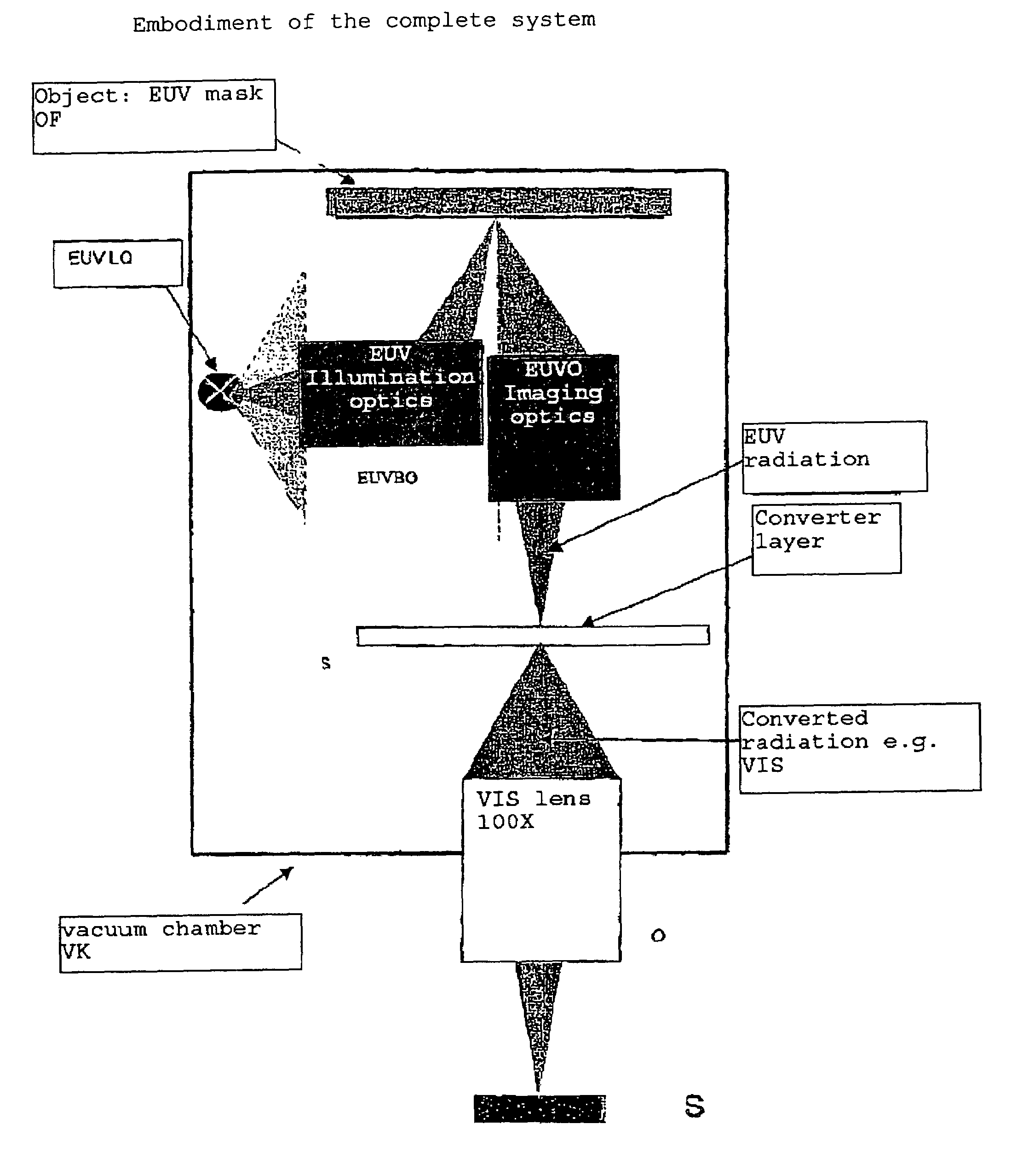
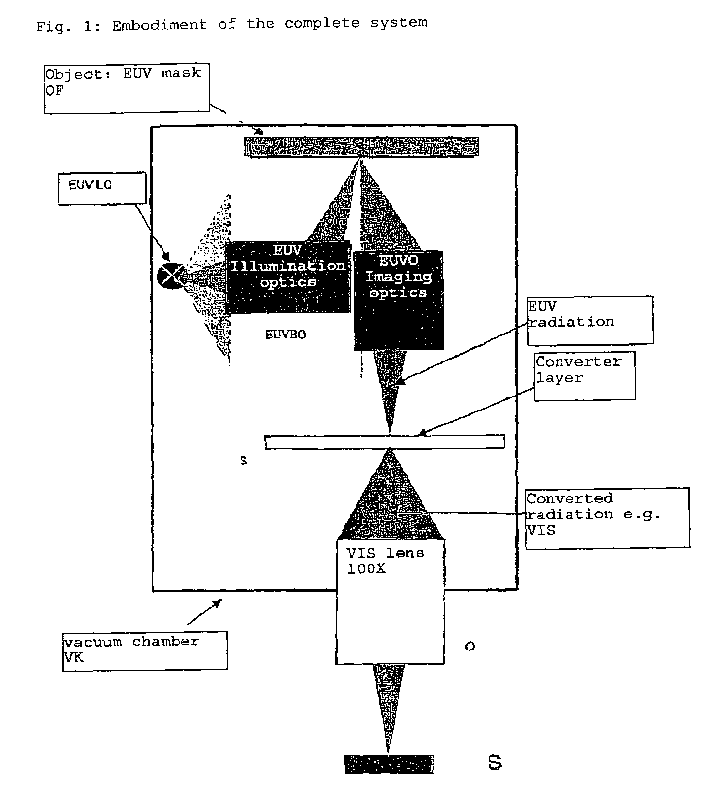
[0015]The present invention is explained more fully on the basis of FIG. 1.

[0016]The object field OF illuminated using an EUV source of light LQ via illuminating optics EUVBO is reproduced on a scintillator S by means of EUV optics EUVO. The scintillator converts the image of the EUV wavelength range into an image of a long-wave range, which is then reproduced on the sensor using an image lens O (i.e. micro lens). In doing so, the imaging lens / the scintillator is used according to the invention in one of the configurations described above.

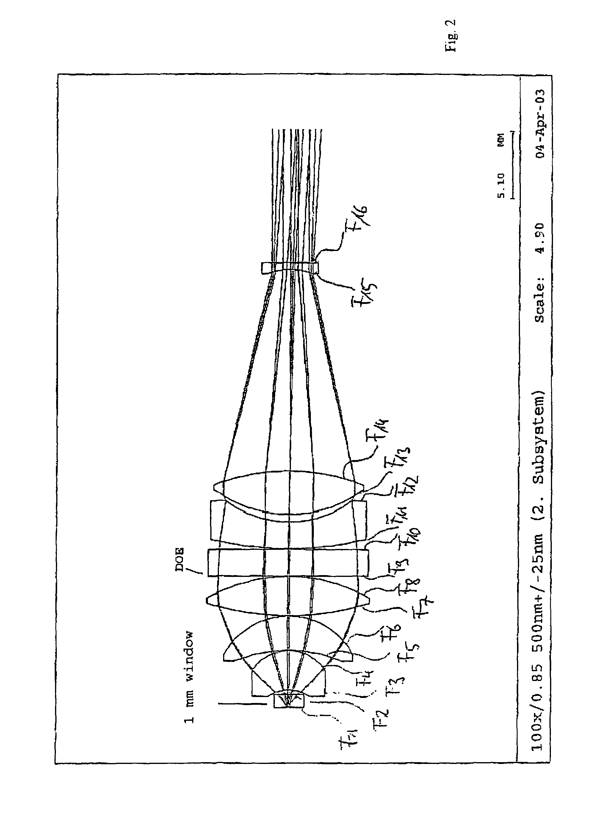
[0017]The lens O is illustrated schematically. A f...


PUM

PropertyMeasurementUnit
wavelengthaaaaaaaaaa
optical imagesaaaaaaaaaa
optical imaging qualityaaaaaaaaaa

Abstract

Apparatus for inspecting objects especially masks in microlithography that are disposed in a vacuum chamber. The apparatus includes a converter for converting illuminating radiation emitted from the object into a radiation of a higher wavelength. A sensor for recording images is disposed outside the vacuum chamber and arranged as an optical interface from the vacuum chamber to the sensor of the converter or at least one part of an image lens is arranged as a window in the vacuum chamber.

Description

CROSS REFERENCE TO RELATED APPLICATIONS[0001]The present patent application is a nationalization of International Application No. PCT / EP2004 / 004161, filed Apr. 20, 2004, which is based on, and claims priority from, German Application No. DE 103 18 560.7, filed Apr. 24, 2003, both of which are incorporated herein by reference in their entireties.FIELD OF THE INVENTION[0002]This invention relates to the field of Microlithography and to devices for inspecting objects that are disposed in a vacuum chamber.BACKGROUND OF THE INVENTION[0003]In order to observe objects or images of objects disposed in vacuum chambers, it is necessary to either insert the observation lens and the sensor (camera) into the vacuum chamber or to observe the objects or images through a vacuum window.[0004]This is particularly required in the case of images using extreme ultraviolet radiation (EUV) if this radiation is converted using scintillators into radiation of a different wavelength and then reproduced on th...

Claims


Application Information

Patent Timeline
Patent Type & Authority Patents(United States)
IPC IPC(8): G01N23/04G01N21/00G01N21/956G03F1/00
CPCB82Y10/00B82Y40/00G01N21/956G03F1/24G03F1/84
Inventor DOBSCHAL, HANS-JUERGENHARNISCH, WOLFGANGSCHERUEBL, THOMASROSENKRANZ, NOBERTSEMMLER, RALPH
Owner CARL ZEISS SMT GMBH
Why Eureka
Try Eureka