Low-power, programmable multi-stage delay cell

a delay cell, low-power technology, applied in the direction of multiple-port active network, electrical apparatus, pulse automatic control, etc., can solve the problem of increasing the delay of the signal being input to the system, and achieve the effect of efficiently managing voltage states and reducing the glitches caused by the transition between various delay stages within the cell

Inactive Publication Date: 2009-04-28
AVAGO TECH WIRELESS IP SINGAPORE PTE
View PDF4 Cites 29 Cited by
  • Summary
  • Abstract
  • Description
  • Claims
  • Application Information

AI Technical Summary

Benefits of technology

[0012]A system, apparatus and method for delaying a signal, such as high-speed signal are disclosed. A multi-stage delay cell is described in which the amount of delay applied to a signal depends on which stages are activated within the cell. In various embodiments of the invention, glitches caused by transitions between various delay stages within the cell are reduced by efficiently managing voltage states on each of the stages. This voltage state management within the delay cell provides a relatively smooth voltage transition as stages are activated or deactivated.
[0014]The amount of delay across the multi-stage delay cell may be adjusted by activating or deactivating certain stages therein. Because of the internal design of the delay cell, the voltage response to changes in the delay period is significantly improved. In particular, the multi-stage delay cell provides state management that allows for a more efficient transition between voltage states between the different stages within the cell as a result of a voltage state on a delay stage being set prior to transitioning to the delay stage.
[0015]In one embodiment of the invention, an input signal may be delayed for a certain time period in order for proper synchronization with another signal, such as a clock. The transition of the delay introduced may be defined by the activation or deactivation of select lines used to control various stages within the cell. The transition of delay from a delay setting to another may be affected by providing programmable control lines. These control lines may provide a sequence of bit values; each of the select lines being assigned to cause a desired control setting. In order to increase the delay value, the number of delay stages introduced in the delay path of the signal being input may be increased. The amount of delay is aggregated to cause an increase in the delay of the signal being input to the system.
[0016]During the operation of the multi-stage delay cell, only components / stages are activated that are associated with the signal path through the delay cell and those related to controlling voltage state(s) on a delay stage(s). This power scheme reduces the amount of power consumed by the delay cell during operation and reduces internal noise.

Problems solved by technology

The amount of delay is aggregated to cause an increase in the delay of the signal being input to the system.

Method used


Image

  • Low-power, programmable multi-stage delay cell
  • Low-power, programmable multi-stage delay cell
  • Low-power, programmable multi-stage delay cell

Examples


Embodiment Construction

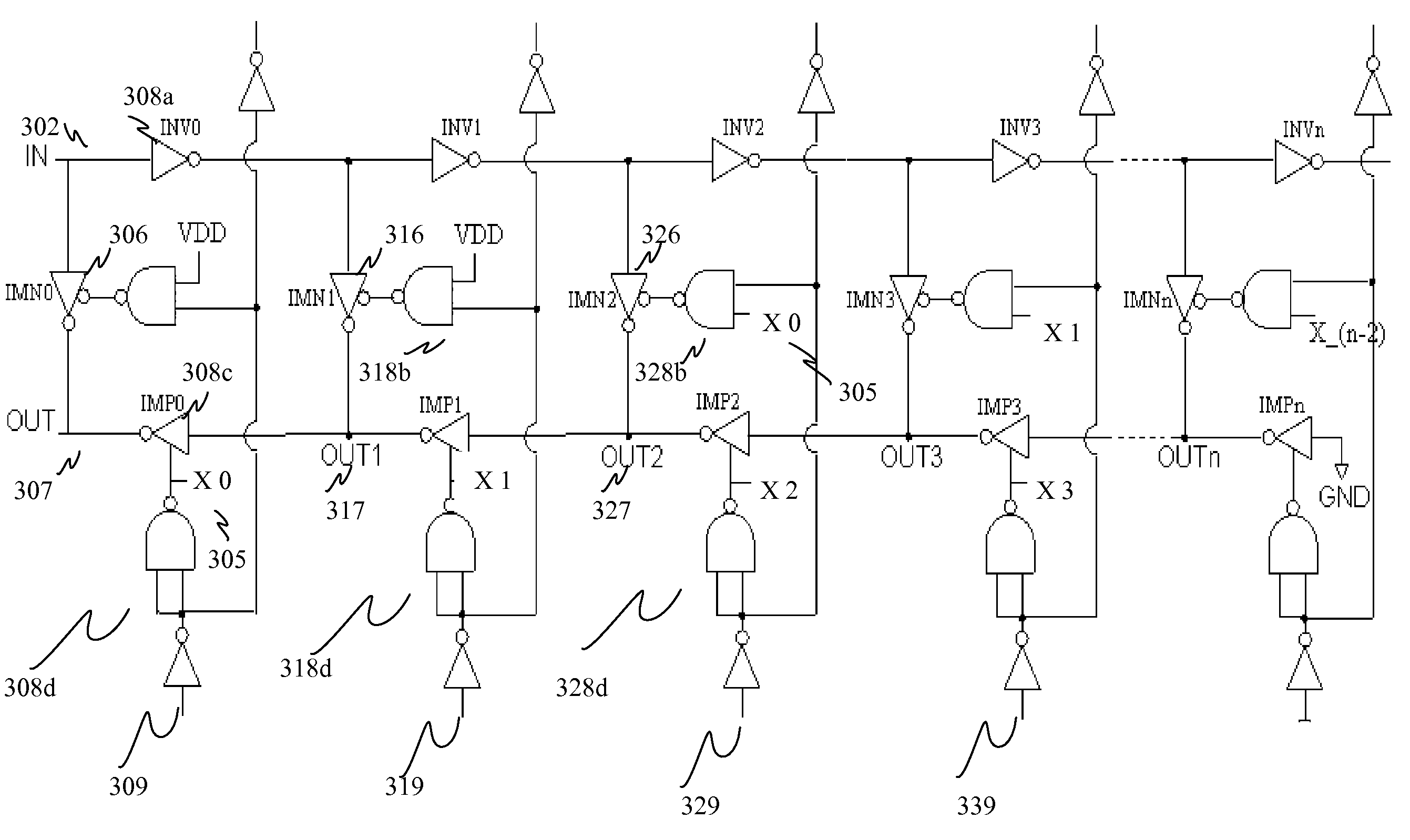
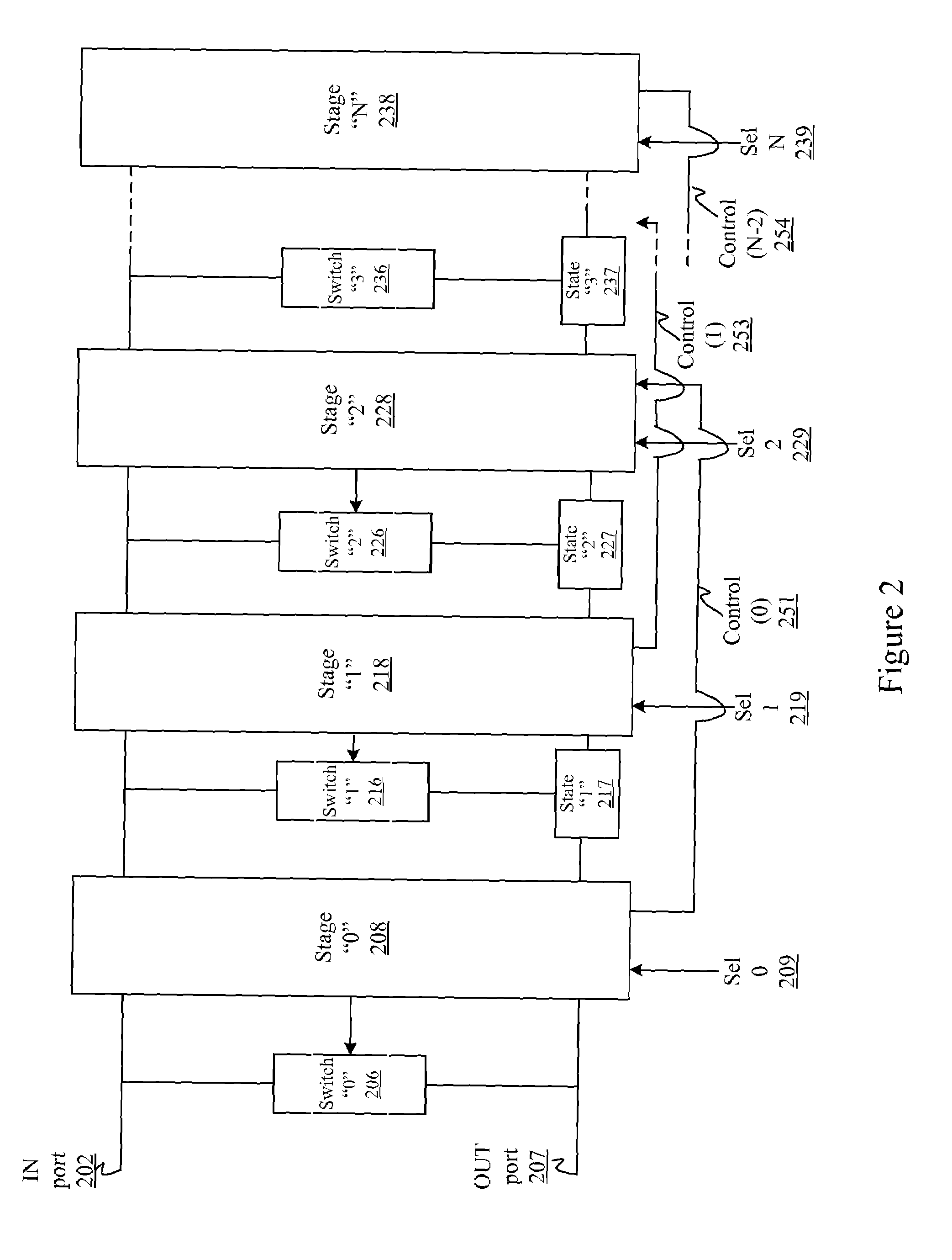
[0022]A system, apparatus and method for delaying a signal, such as a high-speed signal are disclosed. A multi-stage delay cell is described in which the amount of delay applied to a signal depends on which stages are activated within the cell. In various embodiments of the invention, noise caused by transitions between various delay times within the cell is reduced by efficiently managing voltage states on each of the stages.

[0023]In the following description, for purpose of explanation, specific details are set forth in order to provide an understanding of the invention. It will be apparent, however, to one skilled in the art that the invention may be practiced without these details. One skilled in the art will recognize that embodiments of the present invention, some of which are described below, may be incorporated into a number of electronic circuits such as high-speed circuits. Structures and devices shown below in block diagram are illustrative of exemplary embodiments of the...


PUM


Abstract

A system, apparatus and method for delaying a signal, such as a high-speed signal are disclosed. A multi-stage delay cell is described in which the amount of delay applied to a signal depends on which stages are activated within the cell. In various embodiments of the invention, noise caused by transitions between various delay times within the cell is reduced by efficiently managing voltage states on each of the stages.

Description

BACKGROUND[0001]A. Technical Field[0002]The present invention relates generally to signal synchronization, and more particularly, to the design of low-power delay cells.[0003]B. Background of the Invention[0004]The importance and application of electronic technology to day-to-day life is well known. The increasing accuracy of signal processing circuits has allowed ever-increasing amounts of data to be transmitted and received across a communication path in a reliable manner.[0005]Circuits that process these high-speed signals are generally required to be in synchronization with various other signals or clock signals. The signals fed to these high-speed circuits may be “source-synchronized” by timing their relationship with an external clock signal(s). Using this clock, these high-speed circuits provide synchronized sampling of high-speed data signals for further signal processing applications.[0006]Delay cells are an example of devices that may be used to adjust a clock-data phase r...

Claims


Application Information

Patent Timeline
Patent Type & Authority Patents(United States)
IPC IPC(8): H03L7/00
CPCH03H11/26
Inventor HUI, KEVENFANG, TINGSETO, HUI YIN
Owner AVAGO TECH WIRELESS IP SINGAPORE PTE
Why Eureka
Try Eureka