
Wireless communication system for multicast communications

a multicast communication and wireless communication technology, applied in multiplex communication, data switching networks, broadcast service distribution, etc., can solve the problems unable to determine whether currently installed functions are capable of multicast communications or not, and unable to apply ethernet multicast schemes to wireless lans. to achieve the effect of adversely affecting other systems and terminals

Inactive Publication Date: 2009-04-28
NEC CORP
View PDF7 Cites 10 Cited by
  • Summary
  • Abstract
  • Description
  • Claims
  • Application Information

AI Technical Summary

Benefits of technology

Enables multicast communications without centralized management, preventing address overlaps and ensuring that ordinary terminals are not adversely affected, allowing for efficient and effective multicast operations within the wireless LAN system.

Problems solved by technology

Therefore, basically, centralized management is indispensable with regards to the allocation of multicast addresses, and individual systems are not allowed to select and use multicast addresses at their discretion.
However, the conventional process suffers the following problems:
It is doubtful if the Ethernet multicast scheme can be applied to wireless LANs or not.
Consequently, it is uncertain whether currently installed functions are capable of performing multicast communications or not.
However, various terminals that are incapable of receiving such beacon frames and broadcast frames may possibly be caused to malfunction by those frames.
As described above, the conventional wireless LANs require some centralized management for setting multicast addresses and may possibly adversely affect other systems and terminals.
Therefore, the conventional wireless LANs have not effectively be utilized to perform multicast communications that are suitable for use as wireless communications.

Method used


Image

  • Wireless communication system for multicast communications
  • Wireless communication system for multicast communications
  • Wireless communication system for multicast communications

Examples


Embodiment Construction

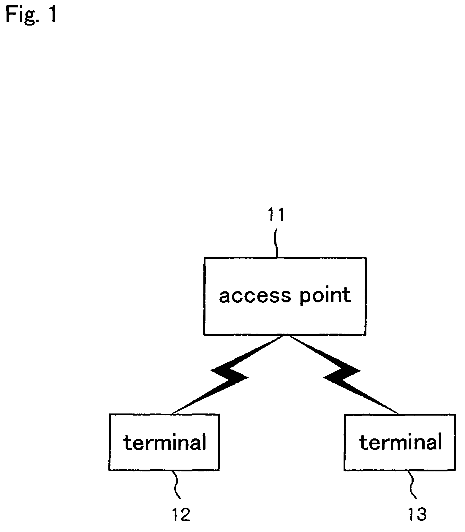
[0036]As shown in FIG. 1, a wireless LAN system according to an embodiment of the present invention has access point 11, terminal 12, and terminal 13.

[0037]In the wireless LAN system, only access point 11 and terminal 13 have a function for performing multicast communications unique to the wireless LAN system, and terminal 12 does not have such a function. Using the function, access point 11 and terminal 13 perform multicast communications to send frames from access point 11 to terminal 13. Terminal 12 which does not have such a function to perform multicast communications does not receive multicast frames.

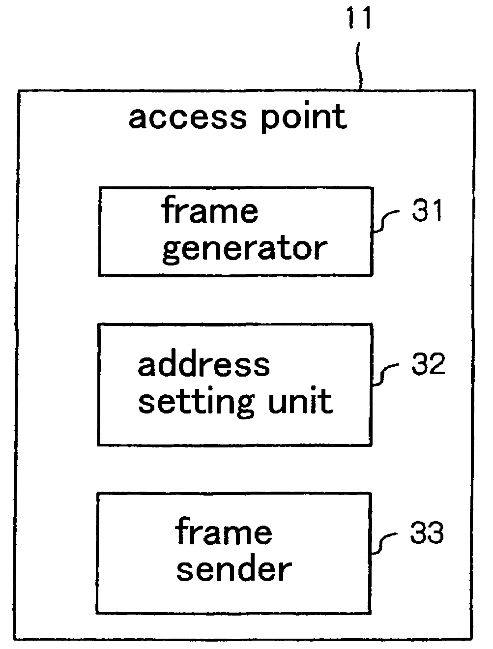
[0038]Access point 11 is a device serving as a junction between a wireless LAN and a wired network. Access point 11 is connected to the terminals through wireless links and allows the terminals to use the wireless LAN. Access point 11 is also capable of performing multicast communications unique to the wireless LAN system.

[0039]For multicast communications, access point 11 uses, a...


PUM


Abstract

A wireless LAN system uses an address that is used by another device than terminals connected to a wireless LAN, as a multicast destination address. An access point sets an address that is used by another device than terminals connected to a wireless LAN of its own, as a multicast destination address. The access point generates a unique multicast frame, which is to be discarded by an ordinary terminal, with the multicast destination address set as a destination address according to a standard frame format, and sends the generated unique multicast frame through a wireless link. A special terminal stores the multicast destination address in advance. The special terminal receives a frame from the access point as a unique multicast frame if the multicast destination address is set as a destination address of the frame.

Description

BACKGROUND OF THE INVENTION[0001]1. Field of the Invention[0002]The present invention relates to a wireless communication system for multicast communications.[0003]2. Description of the Related Art[0004]The widespread use of wireless LANs has made the communication environments much more convenient than when only wired LANs were used. Particularly, wireless LANs are more suitable to broadcast communications and multicast communications than wired LANs because radio waves from an access point reach all terminals that are positioned in the communication range from the access point. Communications with all terminals in the communication range will be referred to as broadcast communications, and communications with certain terminals in the communication range will be referred to as multicast communications.[0005]Wireless LANs employ a packet communication system wherein the destination of each packet is indicated by a destination address. For making broadcast or multicast communications...

Claims


Application Information

Patent Timeline
Patent Type & Authority Patents(United States)
IPC IPC(8): H04L12/56H04W4/06H04W28/06H04W84/12H04W88/08
CPCH04L12/189H04W8/26H04L29/12292H04L61/2069H04W4/06H04W84/12H04W88/08H04L61/5069
Inventor FUJINAMI, MAKOTO
Owner NEC CORP
Learn More