
Wireless network apparatus and method of channel allocation for respective radios

a wireless network and radio technology, applied in the field of network equipment, can solve the problems of unbalanced traffic loading, inability to offer multiple bandwidths to extend link throughput, and inability to adapt to non-co-located radio configurations, etc., to achieve the effect of reducing unbalanced traffic loading

Inactive Publication Date: 2009-04-28
ACCTON TECHNOLOGY CORPORATION
View PDF19 Cites 8 Cited by
  • Summary
  • Abstract
  • Description
  • Claims
  • Application Information

AI Technical Summary

Benefits of technology

The invention provides a method and apparatus for channel allocation for radios in a wireless network to reduce unbalanced traffic loading. The method involves scanning for BSSIDs and recording corresponding characterizing information for every BSSID. The initial channel allocation is compared with predetermined modes, and the best mode is selected for the radios. Traffic within the sectors is monitored, and unbalanced loading is reduced by adding / subtracting a non-overlapped frequency channel of a radio to an unbalanced beam. The apparatus includes an antenna array, beamforming network, radios, and control circuit for controlling the multiplex switch network to establish electrical communication between the antenna elements and the radios based on the predetermined selection of one of a plurality of modes. The technical effects of the invention include reducing unbalanced traffic loading and improving network performance.

Problems solved by technology

However, such loosely integrated and non-co-located radio configuration can neither provide adaptation for beam and / or frequency channel allocation to optimize pattern and / or spectrum efficiencies, nor provide controllable and effective isolations among beams and / or frequency channels.
Further, the independent arrangement of the plurality of radios can neither offer array gain to extend link range, nor offer multiple bandwidths to extend link throughput.

Method used


Image

  • Wireless network apparatus and method of channel allocation for respective radios
  • Wireless network apparatus and method of channel allocation for respective radios
  • Wireless network apparatus and method of channel allocation for respective radios

Examples


Embodiment Construction

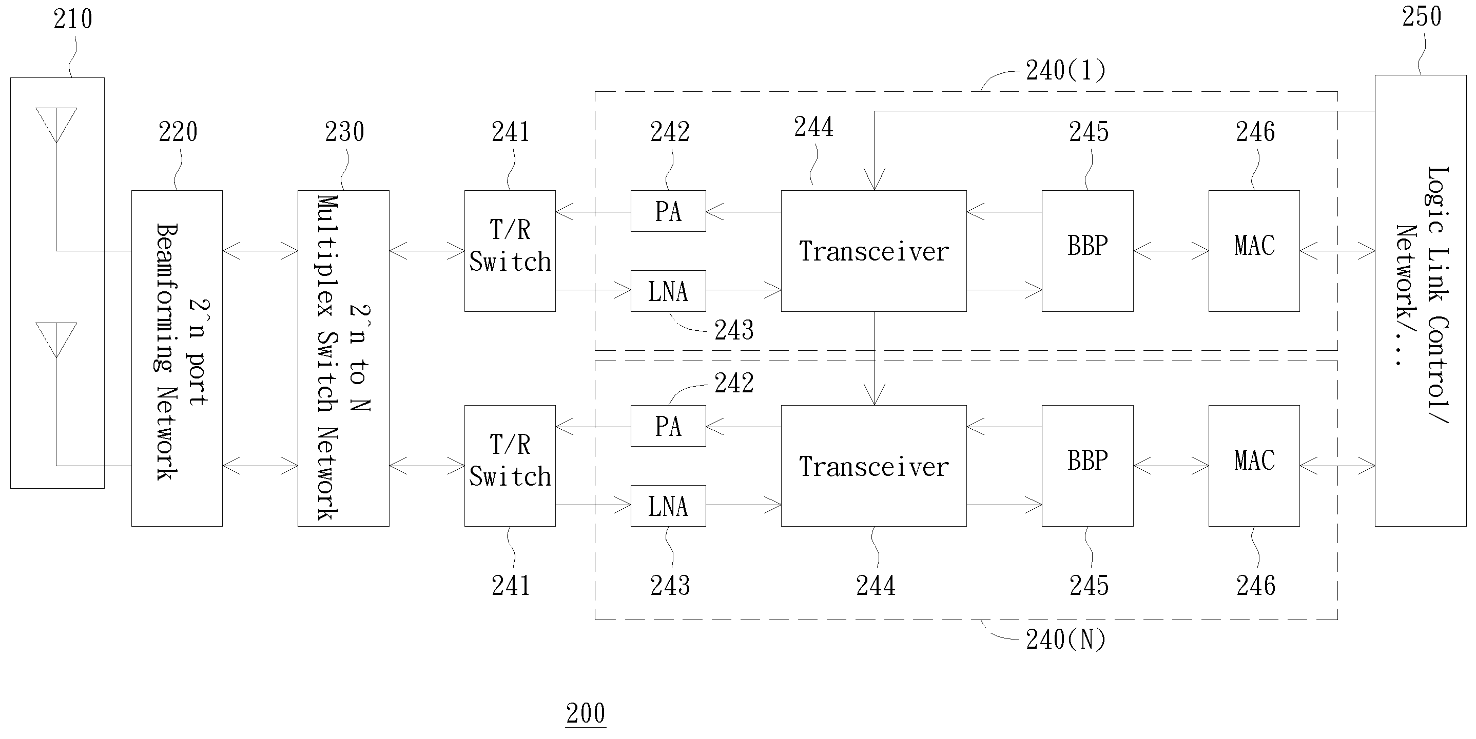
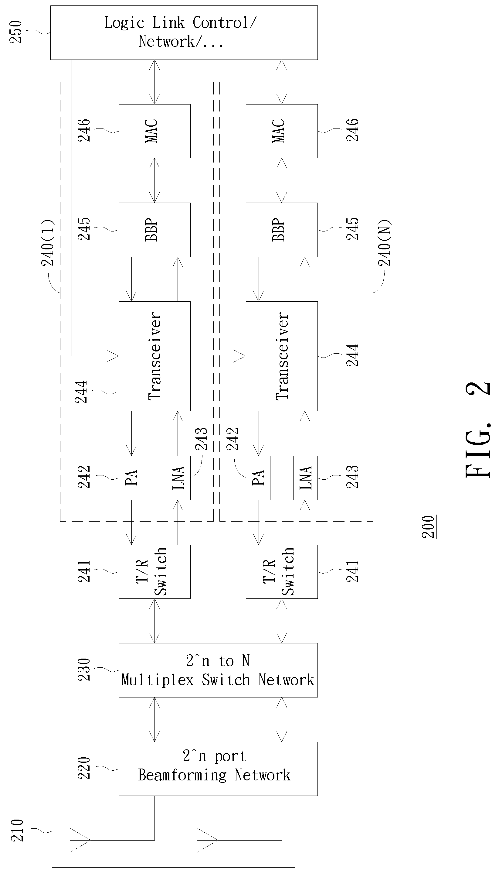
[0024]FIG. 2 shows a wireless network apparatus according to a preferred embodiment of the invention. The wireless network apparatus 200 includes an antenna array 210, a beamforming network 220, a multiplex switch network 230, a plurality of radios 240(1)-240(N), and a control circuit 250.

[0025]To reduce co-channel interference and increase capacity of the system, the coverage area of a wireless base station is usually divided into sub-sections. This coverage area division can be implemented with different types of phased antenna array 210, including planar, sectored, quadrate, hexahedral, and octahedral configurations, as later discussed in detail.

[0026]The antenna array 210 includes a plurality of antenna elements each having an output antenna port for connecting to the beamforming network 220. The number of antenna elements is a 2's multiple. The antenna array 210 thus has 2^n antenna ports corresponding to the respective antenna elements, where n is a positive integer.

[0027]The ...


PUM


Abstract

A method of channel allocation for respective radios is disclosed. The method begins by scanning within sectors of a phased array for retrieval of BSSIDs belonging to each beam of a particular channel in the sectors. Then, corresponding characterizing information is recorded for every BSSID located. Next, an initial channel allocation for the respective radios is formed. The initial channel allocation is compared with a plurality of predetermined channel allocation modes that include a first mode of Point-to-Point (PtP) linkage, a second mode of MultiPoint-to-Point (MPtP) linkage, a third mode of Point-to-MultiPoint (PtMP) linkage, and a fourth mode of MultiPoint-To-MultiPoint (MPtMP) linkage, and a mode out of the predetermined channel allocation modes is selected that best characterizes the initial channel allocation. The radios are configured based on the channel allocation and unbalanced loading is reduced by adding / subtracting a non-overlapped frequency channel of a radio to an unbalanced beam.

Description

BACKGROUND OF THE INVENTION[0001]1. Field of the Invention[0002]The invention relates in general to network apparatus, and more particularly to wireless network apparatus, and method of channel allocation for respective radios.[0003]2. Description of the Related Art[0004]In wireless communications, the need for an increase in capacity is evident as subscriber numbers continue to grow and offset traffic loading, as typically observed in major metropolitan networks.[0005]A solution towards alleviating capacity constraints is to adopt smart antennas for wireless switch system in local and metropolitan networks. With smart antennas, service providers can add network capacity incrementally in areas where it's needed. This flexibility allows the service providers to respond to the characteristics of individual cell sectors, which can have significantly different traffic loads. Owing to such capabilities, smart antennas provide as a cost-effective way for increasing capacity and balancing ...

Claims


Application Information

Patent Timeline
Patent Type & Authority Patents(United States)
IPC IPC(8): H04M1/00
CPCH01Q3/40H01Q25/00H04B7/0617H04B7/086H04W16/04H04W24/00H04W28/08H04W72/04H04W76/02H04W76/10
Inventor LIU, I-RU
Owner ACCTON TECHNOLOGY CORPORATION
Features
  • Generate Ideas
  • Intellectual Property
  • Life Sciences
  • Materials
  • Tech Scout
  • Unparalleled Data Quality
  • Higher Quality Content
  • 60% Fewer Hallucinations
Learn More