Writing implement with clip

a writing implement and clip technology, applied in the field of writing implements with clips, can solve the problems of complicated construction of writing implements, and the inability of the back end part of the clip to prevent the coil spring from falling off perfectly, and achieve the effect of simple construction and easy assembly

Active Publication Date: 2009-05-05
PILOT PEN CO LTD
View PDF11 Cites 12 Cited by
  • Summary
  • Abstract
  • Description
  • Claims
  • Application Information

AI Technical Summary

Benefits of technology

[0006]The cylindrical recess needs to be formed in a depth sufficient for surely restraining the coil spring from easily coming off the cylindrical recess. Consequently, the wall of the barrel needs to have a large thickness and the clip needs to be formed in a large thickness, and thus the cost of the writing implement increases and the degree of freedom of design is reduced. The coil spring of the known writing implement may be inserted into the interior of the barrel to hold the coil spring on the barrel, which, however, complicates the construction of the writing implement and assembling work for assembling the writing implement and requires a space for receiving the coil spring.
[0010]Accordingly, it is an object of the present invention to provide a writing implement simple in construction, easy to assemble and provided with a highly strong clip capable of preventing a coil spring from easily coming off the clip.
[0025]Thus the writing implement of the present invention is simple in construction, easy to assemble and provided with the highly strong clip capable of preventing the coil spring from easily coming off the clip.

Problems solved by technology

The coil spring of the known writing implement may be inserted into the interior of the barrel to hold the coil spring on the barrel, which, however, complicates the construction of the writing implement and assembling work for assembling the writing implement and requires a space for receiving the coil spring.
However, the side walls of the back end part of the clip cannot perfectly prevent the coil spring from falling off.

Method used


Image

  • Writing implement with clip
  • Writing implement with clip
  • Writing implement with clip

Examples


first embodiment

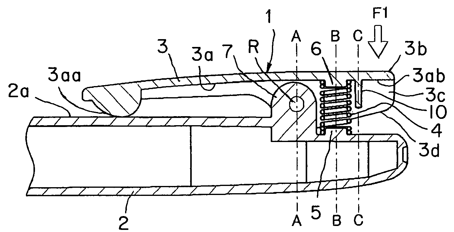
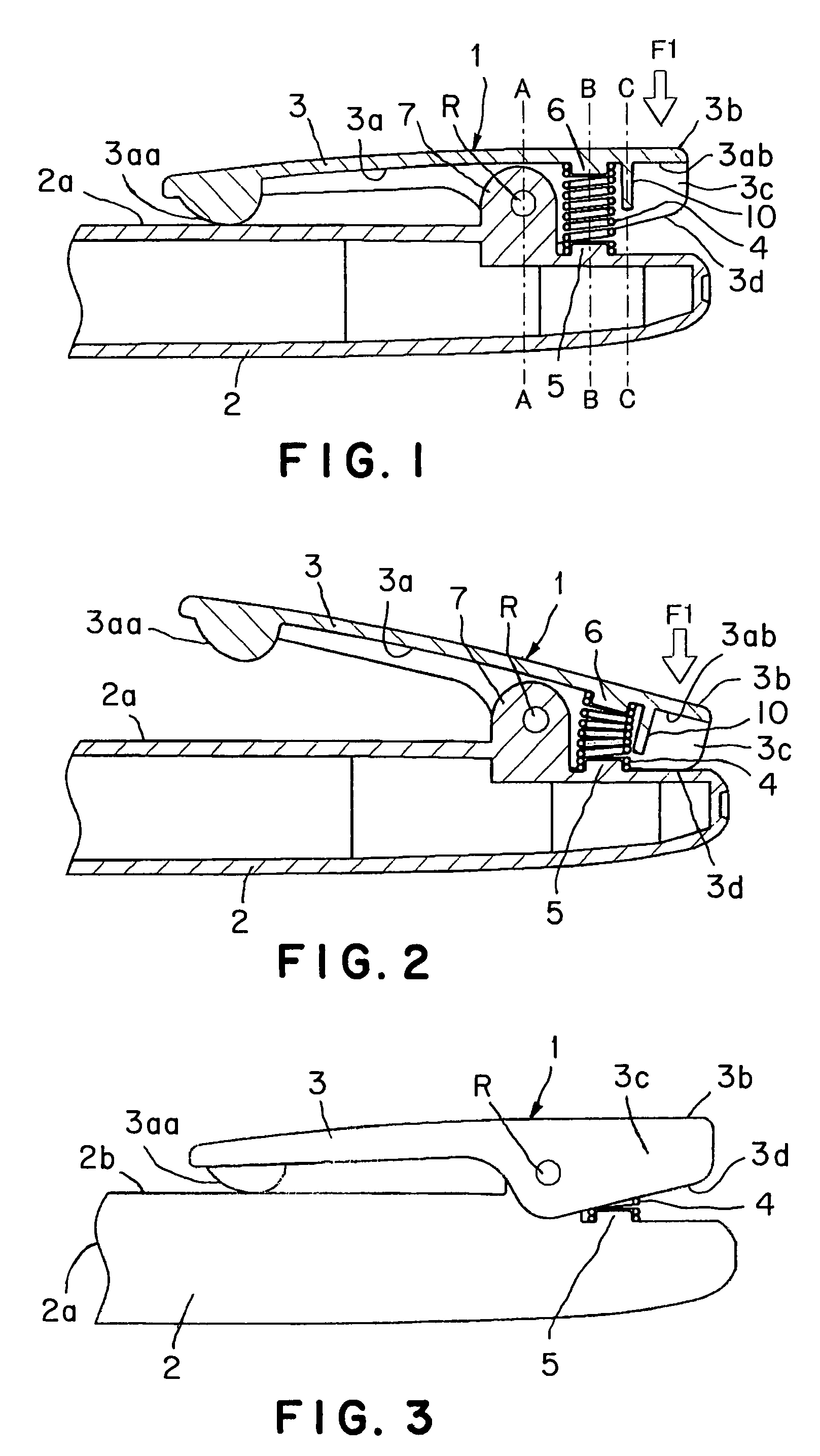
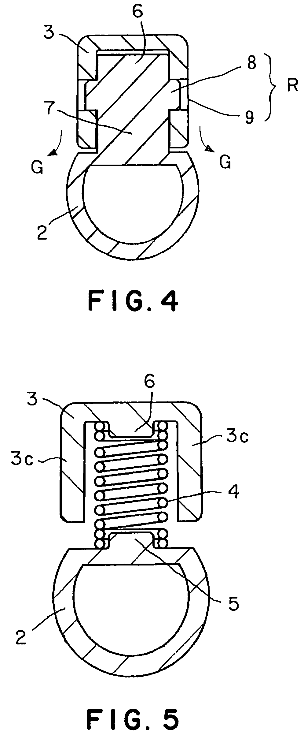
[0046]the present invention will be described with reference to FIGS. 1 to 6.

[0047]A writing implement 1 in the first embodiment includes a barrel 2 forming a tubular body, a clip 3, a pillar 7 formed on the outer surface 2a of the barrel 2, a connecting structure R connecting the clip 3 and the pillar 7, a coil spring 4 extended between the inner surface 3a of the clip 3 and the barrel 2 at a position behind the pillar 7, and a cylindrical projection 5 projecting from the outer surface 2a of the barrel 2 toward the clip 3 to support the coil spring 4 thereon. The coil spring 4 loads the clip 3 such that the inner surface 3a of a front end part 3aa of the clip 3 is pressed elastically against the outer surface 2a of the barrel 2 and permits the clip 3 to be turned on the connecting structure R so that the inner surface 3a of the front end part 3aa of the clip 3 is separated from the barrel 2 when a back end part 3d of a back part 3b of the clip 3 is pressed toward the barrel 2.

[0048...


PUM


Abstract

A writing implement provided with a strong clip is simple in construction and is provided with a coil spring restrained from easily falling off. The writing implement (1, 11, 21) includes a tubular body (2), a clip (3), a pillar (7) formed on the outer surface of the tubular body, a connecting structure R connecting the clip and the pillar, a coil spring (4) extended between the inner surface of the clip and the tubular body and capable of loading the clip such that a front end part (3aa) of the inner surface of the clip is pressed elastically against the outer surface of the tubular body, and a projection (5) formed on the outer surface of the tubular body so as to project toward the clip and fitted in the coil spring. Preferably, the clip is provided with a back wall (10) projecting from a back part (3ab) of the inner surface (3a) of the clip and the coil spring is disposed on the front side of the back wall. The projection (5) has a height not smaller than half the length of the coil spring.

Description

TECHNICAL FIELD[0001]The present invention relates to a writing implement with a clip and, more specifically, to a writing implement including a barrel and provided with a clip continuously elastically loaded such that the inner surface of a front end part thereof is pressed against the outer surface of the barrel and can be separated from the outer surface of the barrel.BACKGROUND ART[0002]There is a generally known writing implement having a barrel and provided with a clip. The clip is continuously elastically loaded such that the inner surface of a front end part thereof is pressed against the outer surface of the barrel and the front end part can be separated from the barrel by pressing a back end part thereof. A clip mechanism for a writing implement disclosed in JP 55-148990 U (Patent document 1) and a clip mechanism for a writing implement disclosed in JP 56-159283 U (Patent document 2) use a coil spring as an elastic member for loading a clip.[0003]JP 55-148990 U (Patent doc...

Claims


Application Information

Patent Timeline
Patent Type & Authority Patents(United States)
IPC IPC(8): B43K23/02
CPCB43K25/02Y10T24/1324Y10T24/135B43K25/00
Inventor ONO, TOSHIHIROKOGURE, MASAHIROMORIYAMA, NORIO
Owner PILOT PEN CO LTD
Why Eureka
Try Eureka