Side trunk mounting structure for two-wheeled motor vehicle

a two-wheeled motor vehicle and side trunk technology, which is applied to vehicle components, other supporting devices, cycle equipment, etc., can solve the problems of less achieve the effect of reducing the degree of freedom in the design of the frame, compromising the exterior appearance of the vehicle, and attractive external appearan

Active Publication Date: 2014-10-21
HONDA MOTOR CO LTD
View PDF15 Cites 20 Cited by
  • Summary
  • Abstract
  • Description
  • Claims
  • Application Information

AI Technical Summary

Benefits of technology

[0015]In the present invention, the plurality of side trunk mounting holes is provided to the rear fender, and the side trunk is mounted directly in the side trunk mounting holes provided to the rear fender.
[0016]In conventional side trunk mounting structures, the side trunk is mounted in side trunk mounting holes formed in the top surface of the rear frame. In this case, since the side trunk mounting holes are opened in the top surface of the rear frame, when the side trunk is removed, part of the rear frame can be seen through the side trunk mounting holes, and the external appearance of the vehicle is compromised. Additionally, the degree of freedom in the design of the frame is reduced by a commensurate amount relative to where the side trunk mounting holes are provided in the top surface of the rear frame.
[0017]In the present invention, this is addressed by having the side trunk mounted on the rear fender; therefore, the side trunk mounting portion on the side of the rear frame cannot be seen from the rear fender, and the vehicle can have a more attractive external appearance. Furthermore, the degree of freedom in the design of the frame is not compromised.
[0018]Since the side trunk mounting holes are provided below the rider's seat, they can be obscured from view when the vehicle is seen from above. If the side trunk mounting holes are obscured from view, the external appearance of the vehicle will not readily be affected even when the side trunk is removed, and the vehicle can have an even more attractive external appearance.
[0019]Since the rear fender is formed from a resin containing glass fiber or carbon fiber, the rigidity of the rear fender can be increased, and the load-bearing capacity can be increased.
[0020]Since hanging parts extend downward in the rear fender, the side trunk can be supported even when the lower engaging arms are short.

Problems solved by technology

However, since the mounting structure according to Patent Document 1 is complex, there is less degree of freedom in the design of the frame, or part of the frame becomes exposed, so that additional consideration must be given to the external appearance.

Method used


Image

  • Side trunk mounting structure for two-wheeled motor vehicle
  • Side trunk mounting structure for two-wheeled motor vehicle
  • Side trunk mounting structure for two-wheeled motor vehicle

Examples


Embodiment Construction

[0040]The preferred embodiments of the present invention are described below with reference to the accompanying drawings.

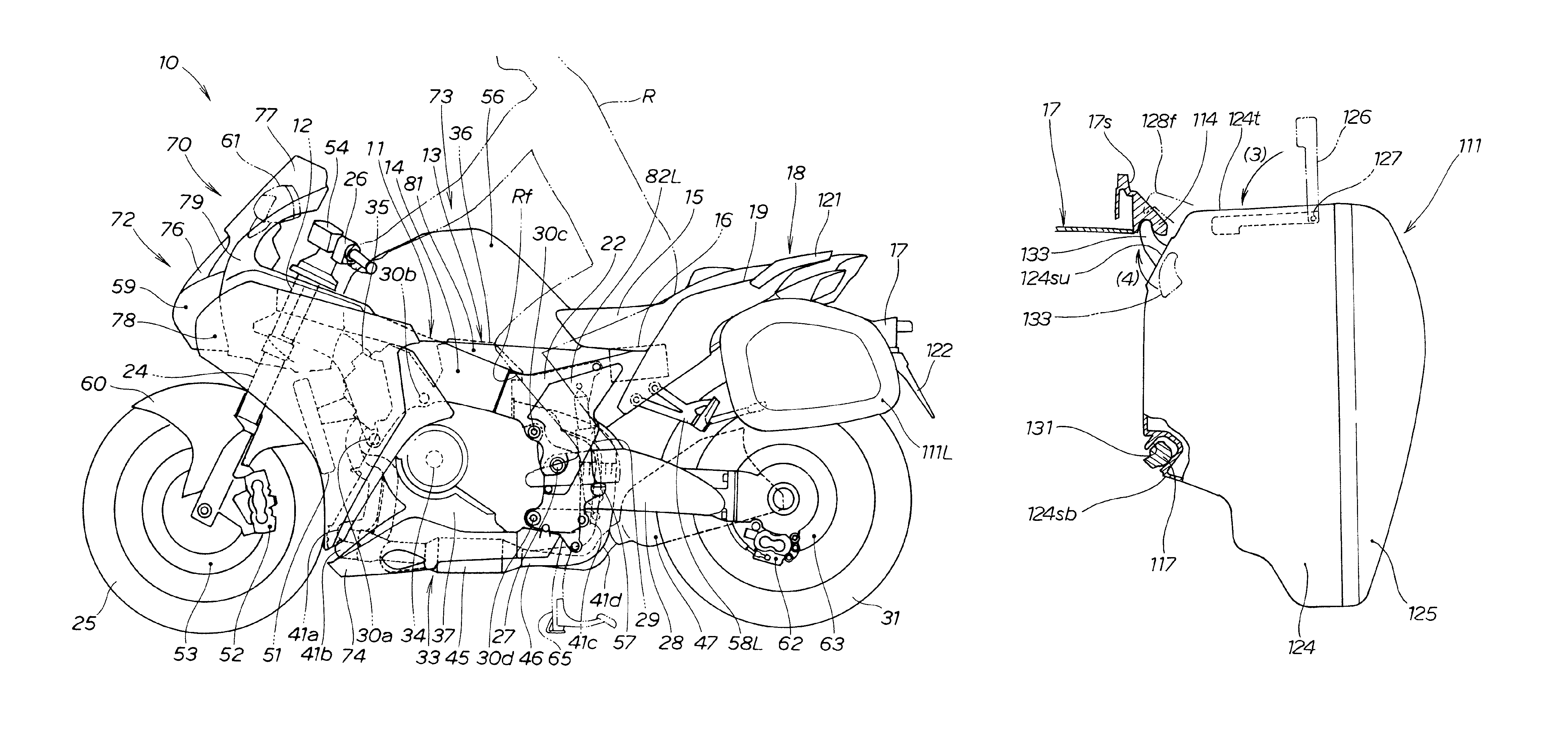
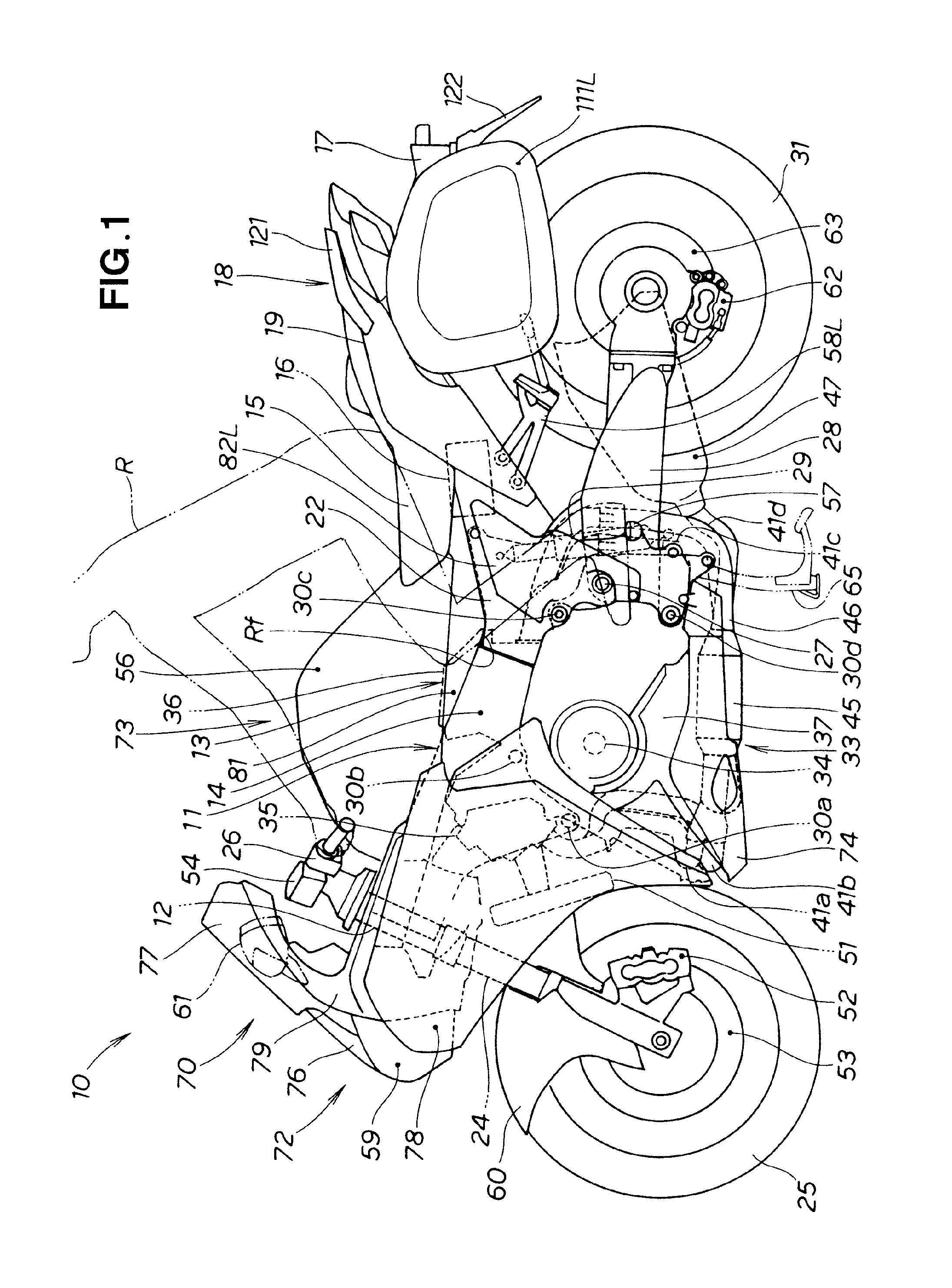
[0041]A two-wheeled motor vehicle 10 comprises a vehicle body frame 11 as shown in FIG. 1. The vehicle body frame 11 is composed of a head pipe 12; a main frame 14 which extends rearward from the head pipe 12 and supports an engine 13; and a rear frame 19 for supporting a rider's seat 15 extending rearward from a top part of a rear end of the main frame 14, mounting a battery 16 and other electrical components and the like, and supporting a vehicle body rear part 18 including a rear fender 17. The main frame 14 includes a pivot plate 22 which is provided to the rear end part of the main frame 14 and which supports a swing arm 28.

[0042]The pivot plate 22 has a pivot shaft 27. The rear swing arm (the swing arm) 28 extends rearward from the pivot shaft 27. A rear cushion unit 29 for absorbing impact is provided between the main frame 14 and the swing arm 28. A rear w...


PUM


Abstract

A side trunk mounting structure which enhances the external appearance of a two-wheeled motor vehicle. Mounting holes (113F, 113r) for mounting the side trunk (111) are formed in a rear fender (17). The side trunk mounting holes are located below a rider's seat (15).

Description

TECHNICAL FIELD[0001]The present invention relates to an improvement in a side trunk mounting structure of a two-wheeled motor vehicle.BACKGROUND ART[0002]There are known side trunk mounting structures of two-wheeled motor vehicles having side trunks detachably provided to either side of a rear part of a vehicle body, such as the structure disclosed in, e.g., Patent Document 1.[0003]The side trunk mounting structure disclosed in Patent Document 1 comprises a rear frame installed on a rear part of a vehicle body, and a trunk support part provided to the rear frame. The rear frame has first concave parts set apart from each other in a longitudinal direction, and a second concave part provided between the first concave parts. The trunk support part is configured from the first concave parts and the second concave part. The side trunk has a side trunk latching means, and is mounted to the rear frame by the side trunk latching means being latched onto the trunk support part.[0004]The rea...

Claims


Application Information

Patent Timeline
Patent Type & Authority Patents(United States)
IPC IPC(8): B62J9/00B62J7/04B60R7/00B62J7/00B62J11/00B62J15/00
CPCB62J9/00B62J9/001B62J7/04B62J15/00B62J9/23B62J9/27
Inventor IIDA, RINATSUHARA, IKUOTORIYAMA, EIJIKOGO, SATOSHIAKITA, HIROTOSHIKAJI, KEIICHI
Owner HONDA MOTOR CO LTD
Why Eureka
Try Eureka