Wind-turbine with load-carrying skin

a wind turbine and load-carrying technology, applied in the direction of machines/engines, mechanical equipment, electric generator control, etc., can solve the problems of limiting the length of the blade, limiting the blade-root diameter, and reducing the service life of the blade, so as to reduce the overall cost, reduce the use of materials, and reduce the effect of structural displacemen

Inactive Publication Date: 2009-05-05
HAMILTON SUNDSTRAND CORP
View PDF50 Cites 36 Cited by
  • Summary
  • Abstract
  • Description
  • Claims
  • Application Information

AI Technical Summary

Benefits of technology

[0014]A wind-turbine includes an “exo-drive” configuration where aerodynamic and gravity loads are transmitted, in the entirety of their path, through structures having a load-carrying skin. These loads are transmitted through these structures starting at a surface of the blade and ending on a wind-turbine foundation. Additionally, the structures carrying the load from essentially an inner blade region (approximately the first 20% of the span) and ending on the foundation are large and have generally common diameter, spacing, and / or dimensional characteristics. This “exo-drive” configuration minimizes material use, structural displacements, and overall cost.
[0015]In one example configuration, the wind-turbine is composed of three main structural systems: a tower; a nacelle, which is rotationally attached to the tower for rotation about a tower axis (yaw axis); and a rotor. Aerodynamic power generated by the rotor is controlled by changing a yaw-angle of the nacelle. The rotor is connected with the nacelle through teeter hinges to prevent large gyroscopic forces produced during yawing from damaging associated structures. The teetering motion allows the gyroscopic forces to be balanced by blade acceleration and aerodynamic damping forces.
[0016]In this example, the nacelle holds a hollow shaft having a relatively large diameter. The hollow shaft is rotationally attached to an aft nacelle structure via at least one bearing for rotation about an essentially horizontal axis. The teeter hinges connect the hollow shaft to a rotor-hub to allow teetering action of the rotor-hub with respect to the hollow shaft. Since the hollow shaft is a thin shell structure, the teeter hinges are necessarily spaced apart with a distance commensurate with an outer diameter of the hollow shaft. The large spacing between teeter hinges enables the rotor hub to have a maximum dimension commensurate with a diameter of the hollow shaft. Blades are fixed to the rotor hub, and as conventional blade bearings are no longer needed, the blade-root attachment also has a maximum dimension commensurate with the diameter of the hollow shaft.
[0018]To minimize weight, and lower stresses, the hollow shaft is configured to have a maximum diameter that is as large as possible. When employing over-land transportation, a maximum outer diameter is limited by road clearances, such as those of over-pass structures, bridges, toll booths, stoplights, etc. In the United States this dimension is approximately four meters. However, for offshore applications, there is no hard limit on maximum diameter when transportation is performed via barges or similar vessels.
[0019]As such, the “exo-drive” large diameter structures in the wind-turbine form most, or all, of an exterior surface of the wind-turbine yielding an additional advantage in reducing the overall number of required components, which in turn reduces cost.

Problems solved by technology

Due to rising costs of the rotor and pitch system that use traditional blades, the blade-root diameter has been limited to sizes below optimum values determined solely on blade structural needs.
Consequently, blades are heavier and costlier than the optimum blade.
At large rotor diameters, the limited, non-optimal, blade-root diameter results in high edge-wise loads that limit the length of the blade and, hence, the annual energy capture.
Consequently, advantages professed by the prior art are limited to relatively small changes to supporting structures and improved service access to a rotor interior.
This also results in the blades being heavier and costlier than the optimum blade.
The net result of all current designs is an increase in total capital for turbine costs, which rises much faster due to rotor diameter limitations than the annual energy capture.
Consequently, lowering the COE is a difficult, and sometimes impossible task.

Method used


Image

  • Wind-turbine with load-carrying skin
  • Wind-turbine with load-carrying skin
  • Wind-turbine with load-carrying skin

Examples


Embodiment Construction

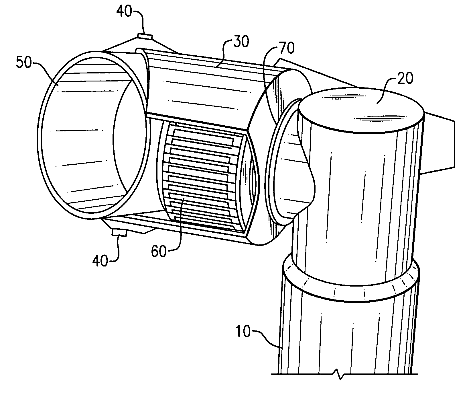
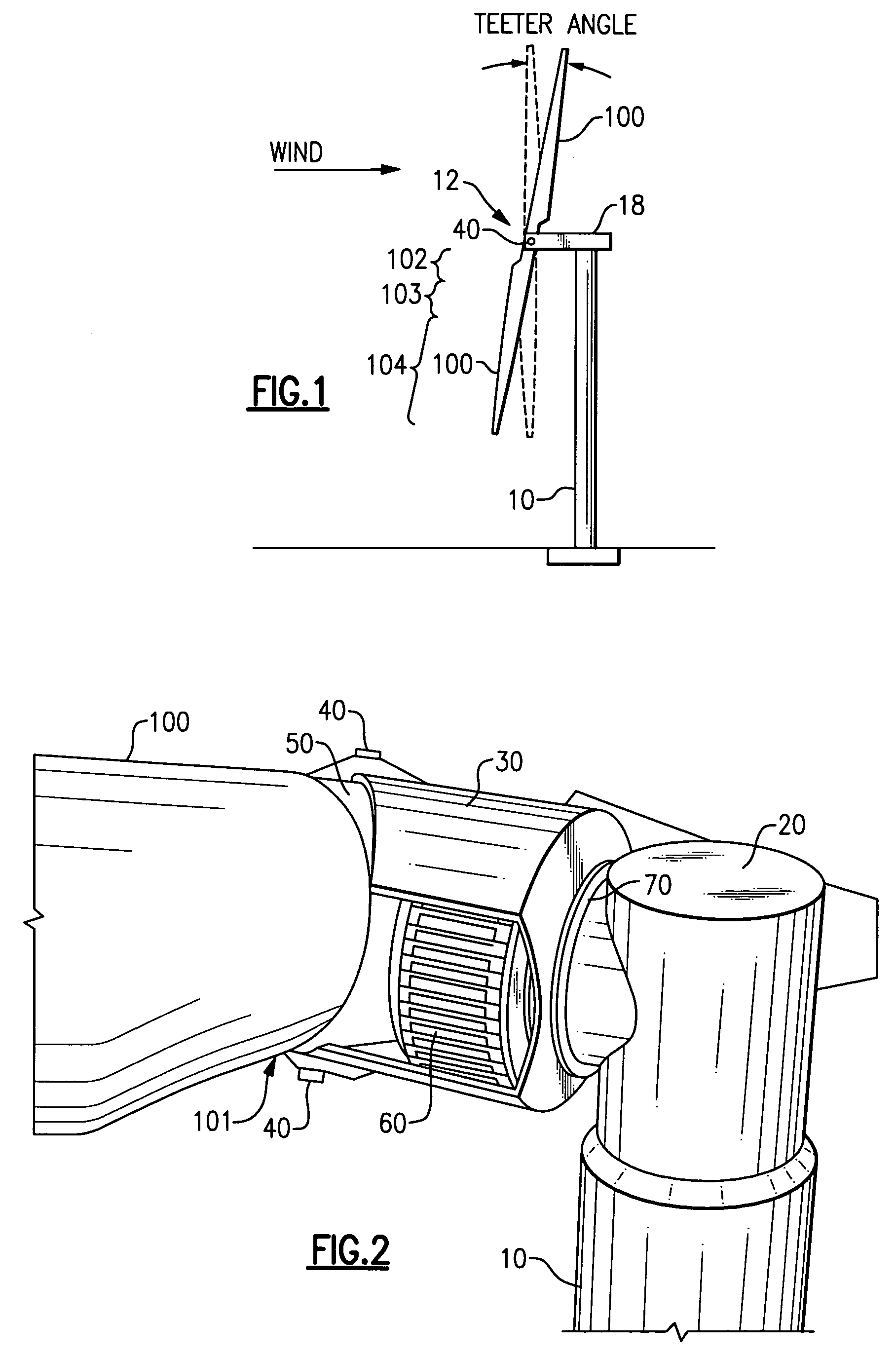
[0030]In reference to FIG. 1, a wind-turbine is composed of three main structural systems including a tower 10, a rotor 12, and a nacelle 18 that is rotationally attached to the tower 10 for rotation about a tower axis (yaw axis). Aerodynamic power generated by the rotor 12 is controlled by changing a yaw-angle of the nacelle 18. Consequently, the rotor 12 must be connected with the nacelle 18 through spaced-apart teeter hinges 40 to prevent large gyroscopic forces produced during yawing from damaging wind-turbine structures. The teetering motion allows the gyroscopic forces to be balanced by blade acceleration and aerodynamic damping forces.

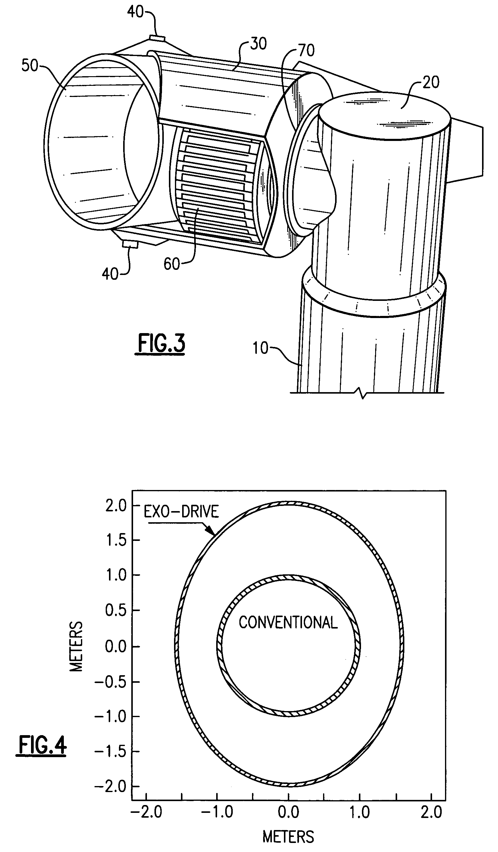
[0031]The nacelle 18 holds a central component of an exo-drive system, namely a hollow shaft 30 (FIGS. 2-3) of a large-diameter, which is rotationally attached to an aft nacelle structure 20 via at least one bearing for rotational motion about an axis that is essentially horizontal. The axis is generally within a range of plus or minus 10 degree...


PUM


Abstract

A horizontal axis wind-turbine includes a stationary support structure, a two-bladed rotor supported by the stationary support structure, and a hollow shaft rotationally attached to the stationary support structure through a bearing. Teeter hinges are spaced apart from each other and connect the hollow shaft to a rotor-hub to allow a teetering action of the rotor-hub with respect to the hollow shaft. The hollow shaft structurally supports the two-bladed rotor with respect to the stationary support structure, with a maximum outer diameter of the hollow shaft being greater than an outer diameter of the bearing.

Description

TECHNICAL FIELD[0001]This invention relates to wind-turbines that generate electrical energy from wind energy, and in particular relates to wind-turbines having a horizontal rotor axis.BACKGROUND OF THE INVENTION[0002]A common goal for commercial wind-turbine manufacturers is to design and produce a wind-turbine that provides the lowest possible cost of energy (COE) throughout the operational life of a wind-turbine. The COE is determined by a comparison of total yearly costs to yearly energy produced. Thus, the COE is minimized by lowering turbine cost while simultaneously increasing the yearly energy capture.[0003]At present, essentially all commercial wind-turbines have a two or three-bladed rotor rotating about a horizontal axis. The rotor is composed of a central rotor hub and the blades, which define a blade-root diameter located at a junction between the central rotor hub and each blade. Each blade is rigidly attached to the central rotor hub with a blade bearing, which preven...

Claims


Application Information

Patent Timeline
Patent Type & Authority Patents(United States)
IPC IPC(8): F03D9/00H02P9/04
CPCF03D1/0658F03D11/04H02K7/1838F05B2220/7066F05B2240/14F05B2240/2022Y02E10/721Y02E10/725Y02E10/726Y02E10/728F03D9/25F03D13/20F03D15/20F03D80/70Y02E10/72
Inventor BERTOLOTTI, FABIO PAOLO
Owner HAMILTON SUNDSTRAND CORP
Why Eureka
Try Eureka