

Method and apparatus for locating foreign objects in the ear canal
- Summary
- Abstract
- Description
- Claims
- Application Information
AI Technical Summary
Benefits of technology
Problems solved by technology
Method used
Image

Examples
Embodiment Construction
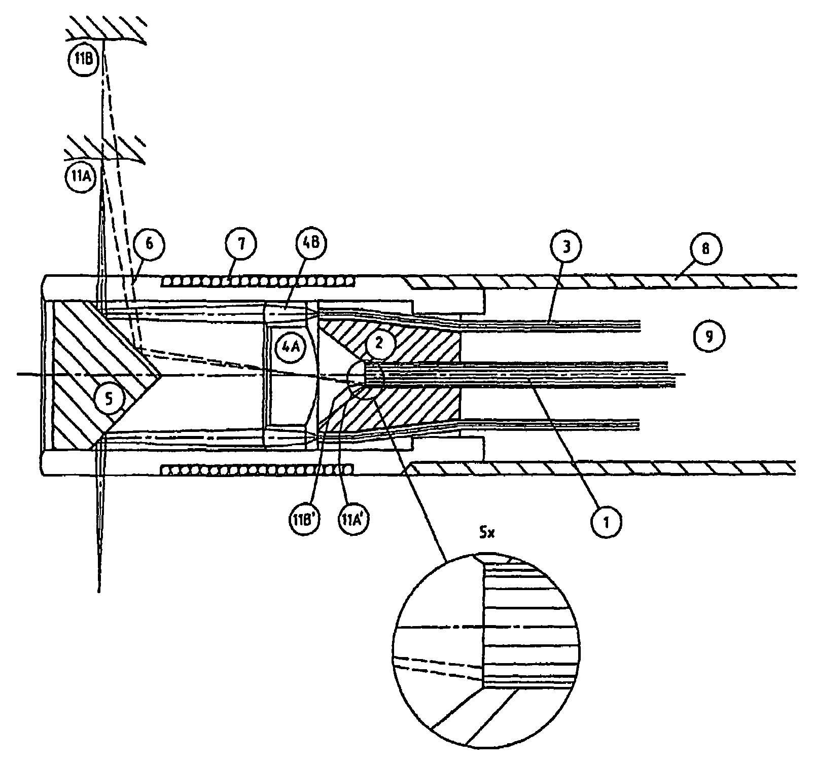
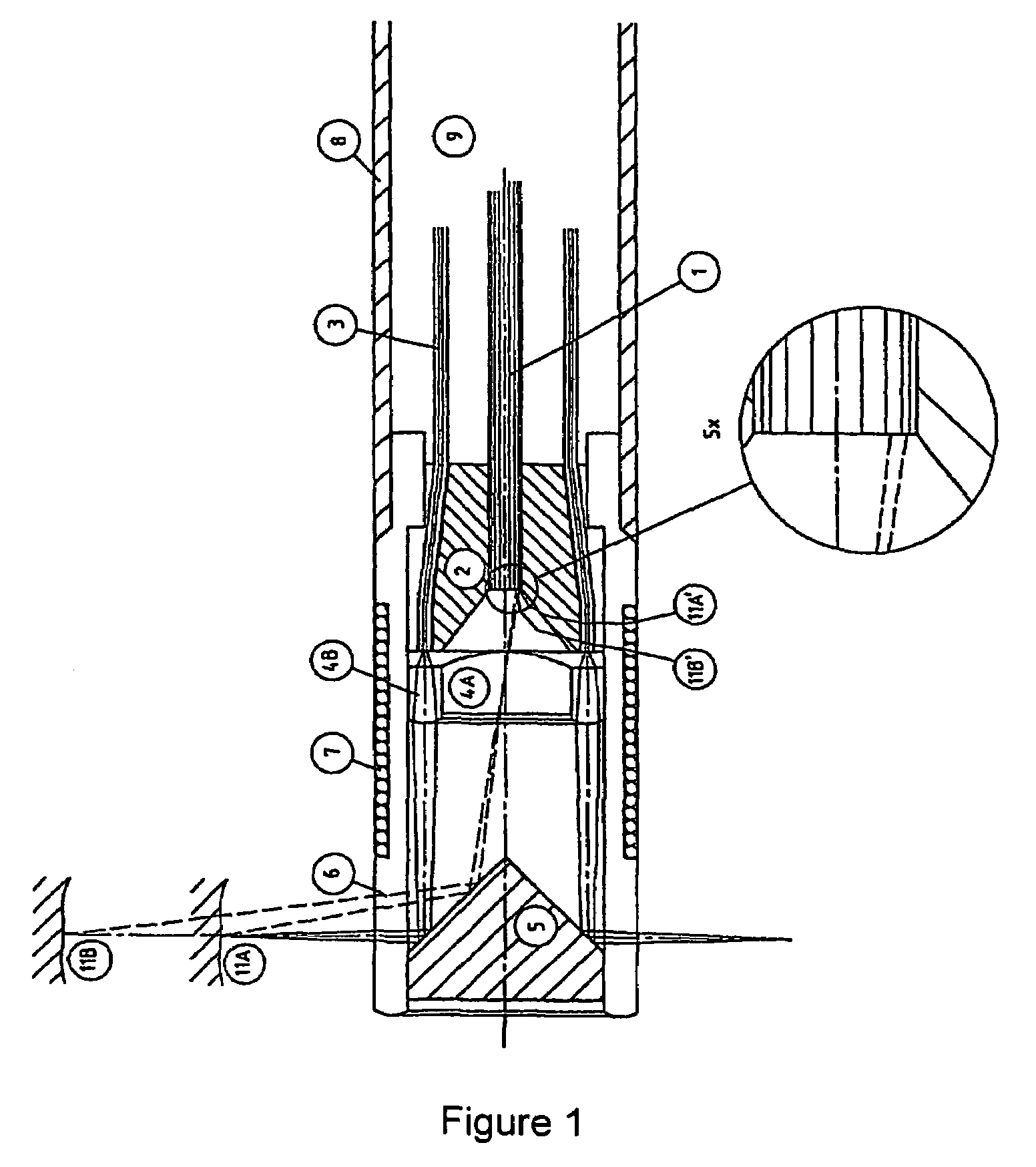
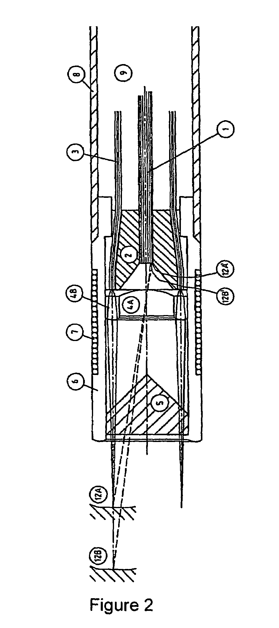
[0044]The probe shown in FIG. 1 has a distal light emitting portion and a rod portion 9, which connects the distal portion to a proximal part (not shown). The rod portion 9 comprises a flexible pipe 8 and a set of light guides 3 and an image guide 1. The image guide 1 is placed centrally in the pipe 8, and the light guides 3 are arranged between the pipe 8 and the image guide 1. Near the tip of the probe the light guides 3 are fastened between an inner bushing 2 and an outer tube 6. An annular lens 4B is arranged at the bushing 2 to capture the light emitting from the light guides 3, in order to focus said light. The focused light beam is directed to a first portion of a mirror 5 mounted at the tip of the tube 6. The first portion of the mirror 5 has a circumferential conical plane with a top angle of 45°. Thereby the focused light beam emitted from the lens 4B will be directed in a right angel away from the longitudinal axis of the probe, and towards the surrounding canal wall 11. ...
PUM
 Abstract
Description
Claims
Application Information