High pressure tube cleaning apparatus

a cleaning apparatus and high-pressure technology, applied in the direction of cleaning heat-transfer devices, rotary device cleaning, cleaning with liquids, etc., can solve the problems of affecting the heat-transfer efficiency, scale and other undesired residues, corrosion of the bore and exterior walls of the heat-transfer tubes, and reducing the accumulation of residues

Inactive Publication Date: 2009-05-12
GARMAN DANIEL T
View PDF2 Cites 27 Cited by
  • Summary
  • Abstract
  • Description
  • Claims
  • Application Information

AI Technical Summary

Benefits of technology

[0011]It is accordingly a primary object of the invention to provide a high-pressure tube cleaning assembly wherein a spray hose and spray nozzle can be directed at high rotational and axial rates by the assembly as the nozzle is directed through each tube or other appliance being cleaned.
[0012]It is a further object of the invention to provide an assembly that includes a rotationally driven hose reel that arranges the spray hose in a fashion that avoids unbalancing the equipment relative to a longitudinal, rotational drive axis.

Problems solved by technology

A problem especially common to heat exchangers and evaporators is that over time the bore and exterior walls of the heat exchange tubes develop corrosion, scale and other undesired residue.
The buildup of residue decreases and / or generally adversely effects the heat transfer efficiencies.
Operating costs for fuel, in turn, increase.
The task is typically performed manually and is therefore costly and time consuming, especially for large heating and cooling plants.
Although offering advantages, the efficiency of the latter system is severely restricted by vibrations that occur due to unbalanced conditions that can occur at the equipment during typical use.
Extreme vibrations have particularly been experienced at speeds approaching 60 rpm, which severely limits the utility of the equipment.

Method used


Image

  • High pressure tube cleaning apparatus
  • High pressure tube cleaning apparatus
  • High pressure tube cleaning apparatus

Examples


Embodiment Construction

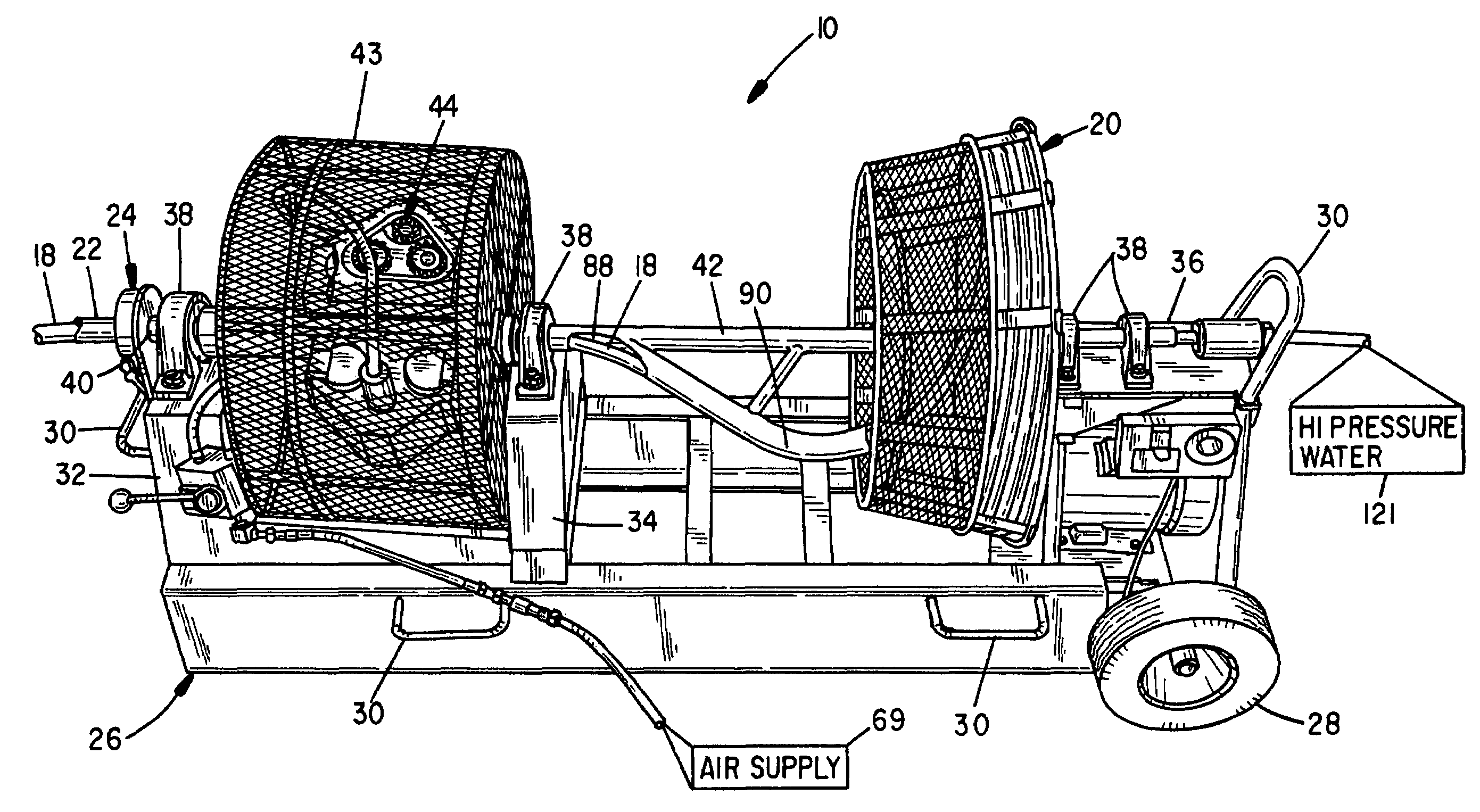
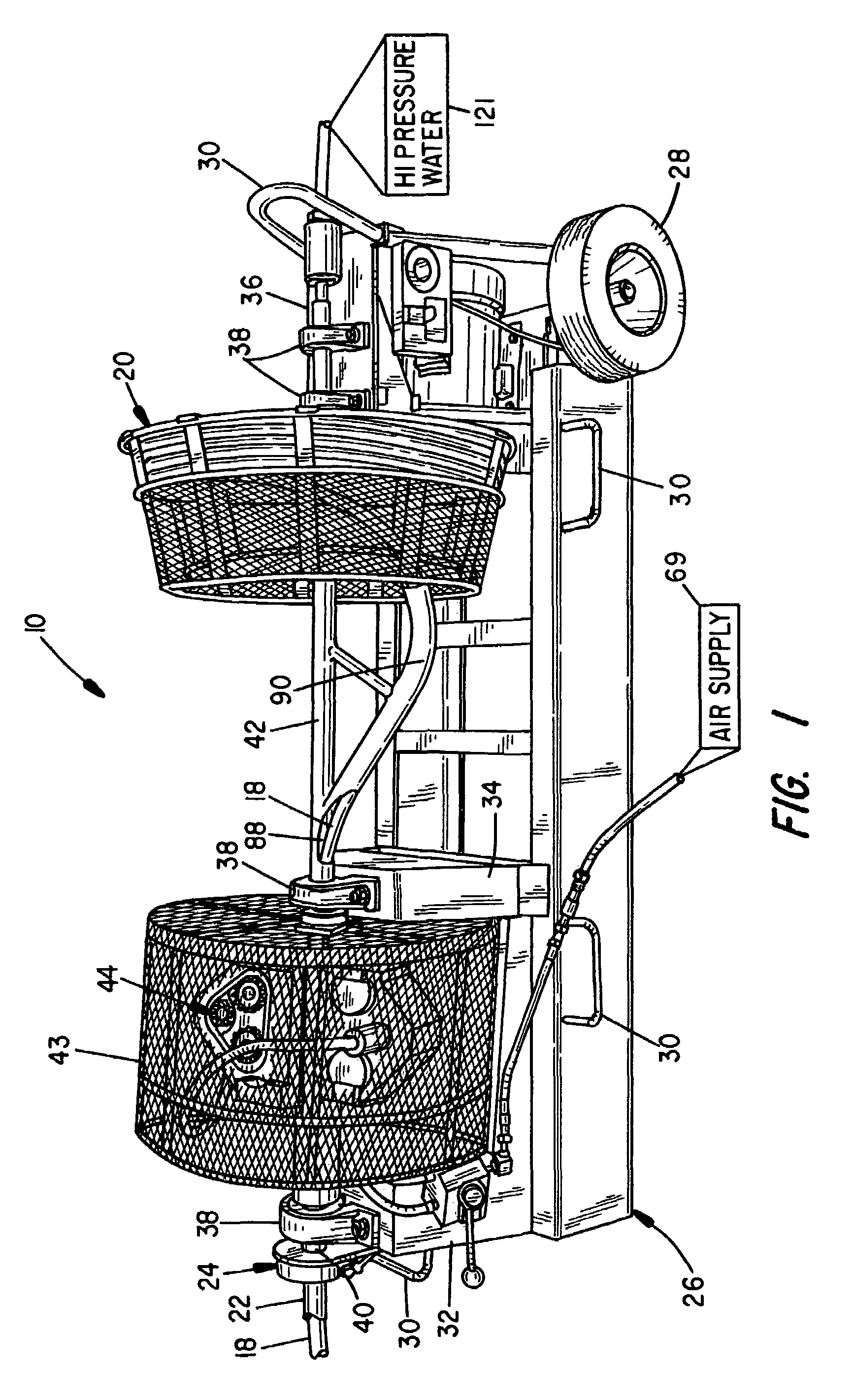
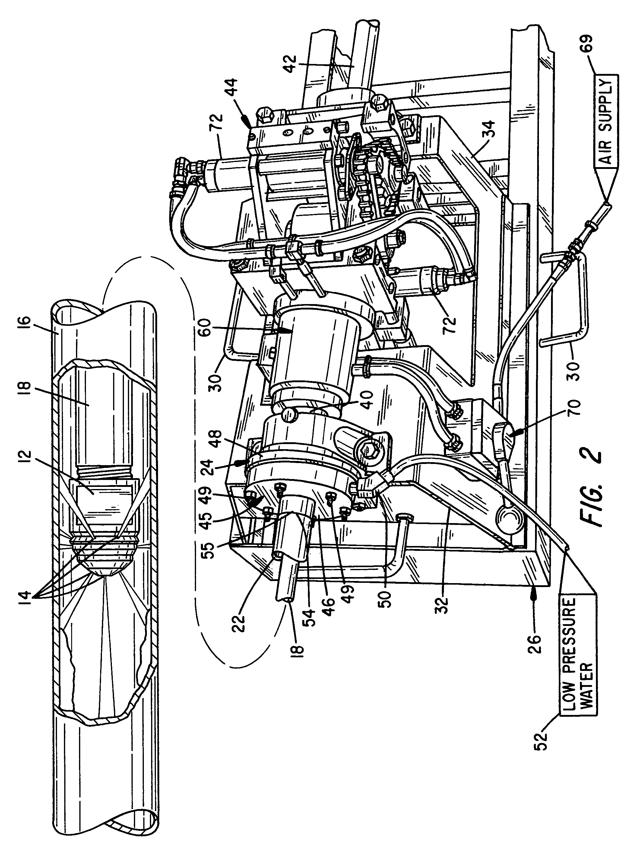
[0067]Referring to FIG. 1 a perspective drawing is shown to the portable, high-pressure spray cleaning assembly 10 of the invention. The assembly 10 finds particular application for on-site cleaning of heat transfer tubes in commercial and industrial heat exchangers. A spray head 12 having a desired number of orifices 14, reference FIG. 2, directs a number of high-pressure (e.g. 200 to 50,000 psi) streams of water against the bore walls of a heat transfer tube or pipe 16 to dislodge and wash scale and residue from the tube walls 16. The spray head 12 is rotated and axially extended and retracted from the tube 16 to most advantageously direct the spray streams from the orifices 14.

[0068]A suitable length of hose 18 is secured to the spray head 12 and is deployed and stored at a hose spool or collection reel assembly 20. The hose 18 is constructed to withstand the normal anticipated working conditions and pressures. The hose 18 is typically constructed of several layers of water imper...


PUM


Abstract

An assembly for rotating and axially directing a high pressure spray hose and spray head to clean residue from tubing bores. Modular, remotely controlled subassemblies are concentrically aligned and mounted to a hose drive framework to rotate in synchrony and direct a high-pressure water hose and spray head. A hose drive assembly controls hose rotation and axial hose movement via biased pinch wheels. A resilient, eccentric linkage controls pinch wheel pressure. A layering arm uniformly layers the hose at a hose reel. Rotational sensors and / or a pneumatic booster and a disk brake assembly facilitate non-kinking hose collection and release without spillage. A re-configurable hose support framework contains a driven walking beam having drive assemblies that laterally and vertically index a hose support and control the inclination of the walking beam.

Description

RELATED US APPLICATION DATA[0001]This is a continuation-in-part application of U.S. Ser. No. 10 / 673,748, filed Sep. 29, 2003, now U.S. Pat. No. 7,178,534; which is a continuation-in-part application of U.S. Ser. No. 09 / 811,064, filed Mar. 16, 2001, now U.S. Pat. No. 6,626,195.BACKGROUND OF THE INVENTION[0002]The present invention relates to cleaning equipment for tubes and piping and, in particular, to high-pressure water spray systems for cleaning the bores of tubes mounted in a variety of equipment, such as heat exchangers, falling pressure evaporators and the like.[0003]Industrial piping systems of all types frequently require cleaning. A problem especially common to heat exchangers and evaporators is that over time the bore and exterior walls of the heat exchange tubes develop corrosion, scale and other undesired residue. The buildup of residue decreases and / or generally adversely effects the heat transfer efficiencies. Restriction of the bore is especially critical. Operating c...

Claims


Application Information

Patent Timeline
Patent Type & Authority Patents(United States)
IPC IPC(8): B08B9/045F28G3/16
CPCB08B9/045B08B9/0433
Inventor GARMAN, DANIEL T.
Owner GARMAN DANIEL T
Why Eureka
Try Eureka