Flat screen television support system

a technology for supporting systems and flat-screen televisions, applied in the direction of machine supports, furniture parts, chairs, etc., can solve the problems of complex installation, screen aesthetically challenging the arrangement of other furnishings, and the inability to develop furniture-top stands

Active Publication Date: 2009-05-12
WHALEN LLC
View PDF54 Cites 133 Cited by
  • Summary
  • Abstract
  • Description
  • Claims
  • Application Information

AI Technical Summary

Benefits of technology

[0007]The present invention is directed to the support of a flat screen television relative to a piece of furniture that addresses the problems described above. First, the invention eliminates any need to mount the flat screen television on a wall surface. Second, the present invention eliminates the need for furniture-top stands to support the screen on the surface of the furniture, thus leaving the entire surface area clear for other purposes, accessories, etc. Third, the flat screen television is supported a desired distance above the furniture top surface and at a position between the front and rear edges of the furniture top surface. In this regard, the supported flat screen presents the illusion of “floating” above the surface of the furniture top, while at the same time being positioned forwardly and away from the back of the furniture or the wall against which the furniture may be situated. More particularly, the device may be installed on an existing piece of furniture without cosmetically altering the furniture. The support device may be sold alone for use on existing furniture, or it could be sold as part of a piece of furniture. These aspects of the invention are provided in the several exemplary embodiments described herein.
[0008]In one embodiment, and in its simplest construction, the supporting device comprises a base for supporting the weight (up to 200 pounds) of the screen on a floor surface. A column extends upwardly from the base and is connected to the back of the piece of the furniture by a bracket, or the like. A cantilever support arm extends forwardly from the column, having a free end with a screen mounting member connected thereto. In a more preferred embodiment, the column has a tubular or polygonal cross-section. In addition to providing structural rigidity and strength to the support, the hollow cross-section is readily adaptable for the concealed routing of cables for the flat screen television, speakers, etc. Optionally, a number of spaced apertures are formed in the column for the ingress and egress of the electrical cables being routed through the column.
[0009]In another embodiment, the support device comprises a multi-part construction including a pedestal and an upper support. The pedestal comprises a base for supporting the weight of the screen on a floor surface, a column extending upwardly from the base, and a bracket for connecting the column to the back of the furniture. The upper support comprises a post that is vertically adjustable and slideably received within the column, a cantilever support arm, and a screen mounting member. When the screen mounting position is determined, the upper support is secured in position with the column. The vertical adjustability provides the user with even greater flexibility in adjusting the support to a height that accommodates screens of various sizes, while allowing the user to position the screen the desired distance above the top of the furniture.
[0010]In yet another embodiment, the piece of furniture is constructed so that the pedestal of the support is built into or secured to the back of the furniture in such a way as to eliminate the base. Accordingly, the furniture structure itself supports the weight of the flat screen.

Problems solved by technology

These portable models, however, still comprised large picture tubes, wiring, and circuitry enclosed within an outer casing; therefore, these portable models still required a sizable surface area for supporting them and, because the picture tubes were rather deep, a surface area with considerable (24 inches or more) depth.
These installations are complicated and involve not only mounting the screen on the wall, but also the routing of video and speaker cabling within the walls or behind large pieces of furniture.
Further, such installation of the screen aesthetically challenges the arrangement of other furnishings within the chosen room.
Attempts to develop furniture-top stands have been met with only marginal success since these taller, longer screens, while thinner, can still easily monopolize the entire top or shelf of a large piece of furniture to the exclusion of other items or accessories.

Method used


Image

  • Flat screen television support system
  • Flat screen television support system
  • Flat screen television support system

Examples


Embodiment Construction

[0018]Certain exemplary embodiments of the present invention are described below and illustrated in the attached Figures. The embodiments described are only for purposes of illustrating the present invention and should not be interpreted as limiting the scope of the invention, which, of course, is limited only by the claims below. Other embodiments of the invention, and certain modifications and improvements of the described embodiments, will occur to those skilled in the art, and all such alternate embodiments, modifications and improvements are within the scope of the present invention.

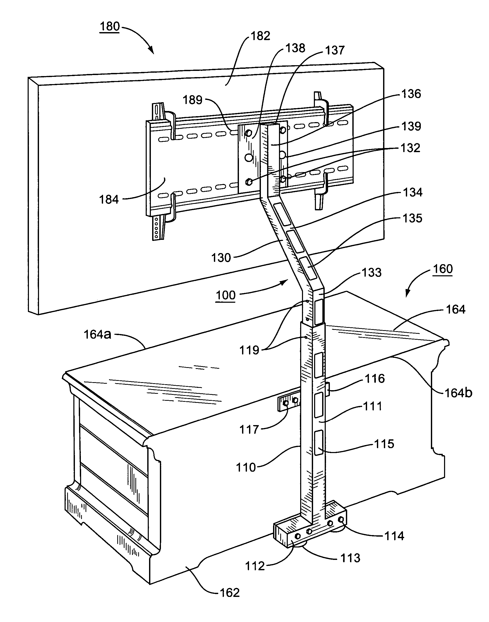
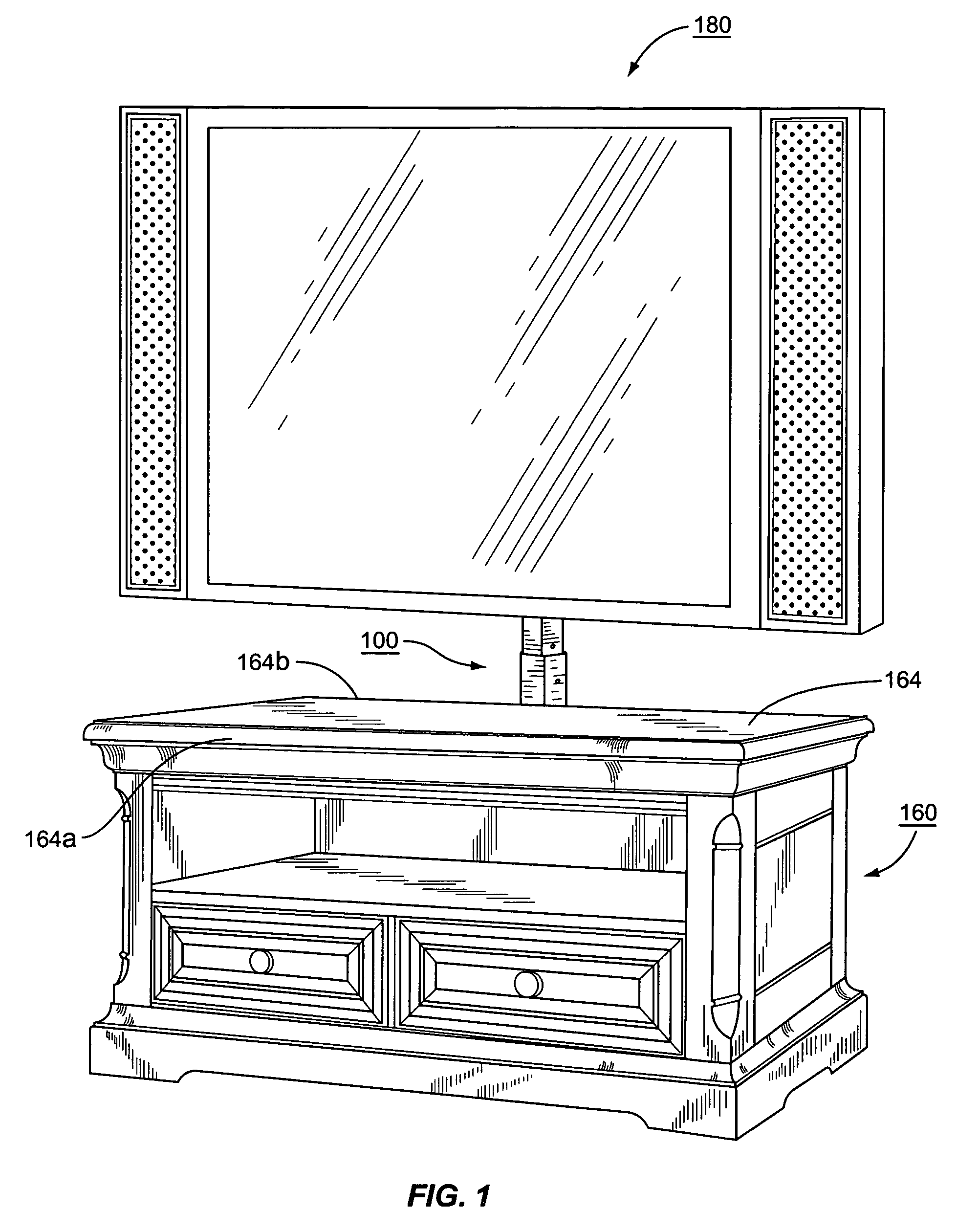
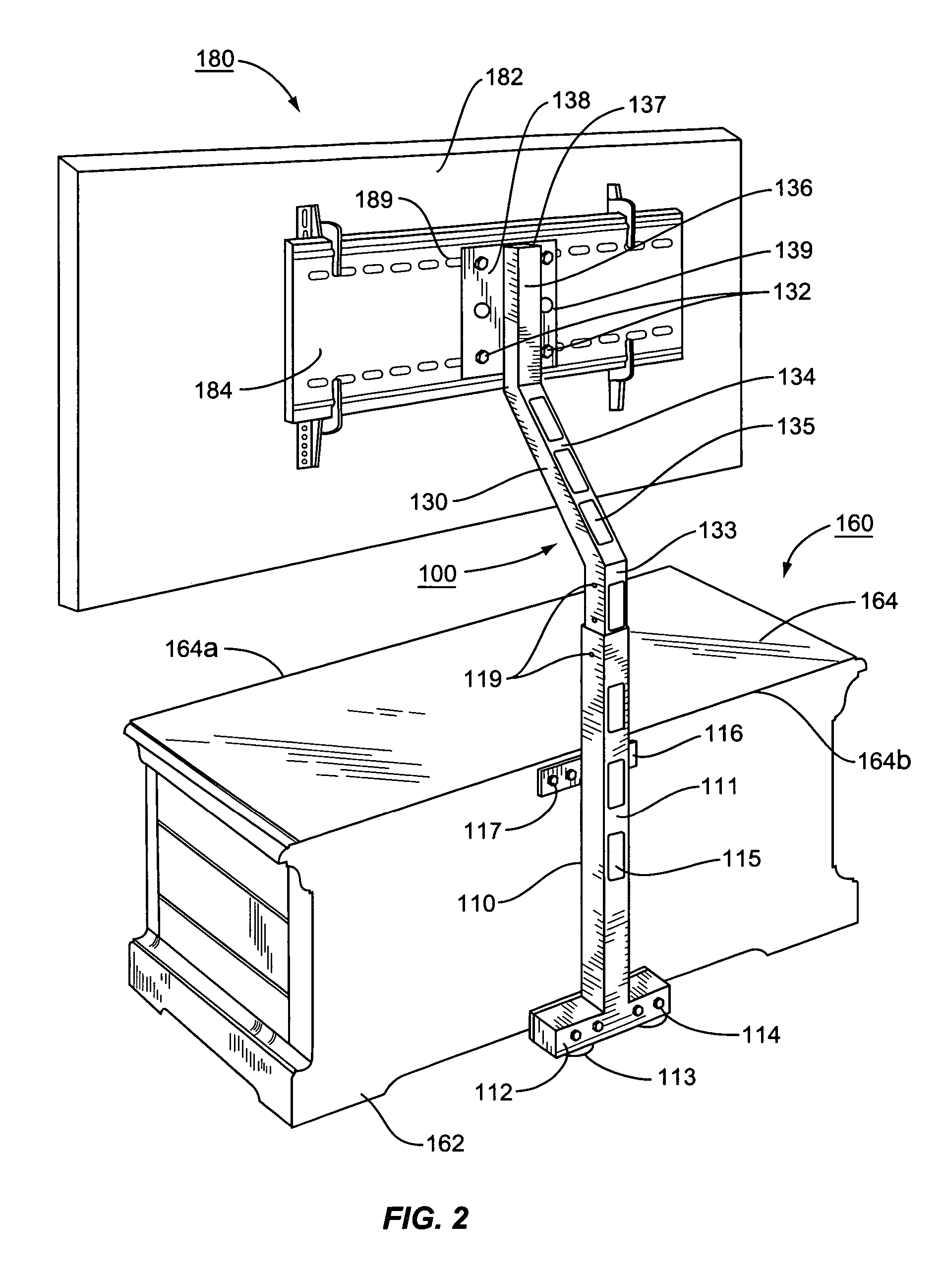
[0019]Shown generally in the environmental view of FIG. 1, and in detail in FIGS. 2 through 5, the present invention is directed to the idea of supporting a substantially flat screen television 180 over a piece of furniture 160 with a support device 100. So supported by the device 100, the flat screen television 180 is supported above the surface 164 of the furniture at a prescribed point between th...


PUM


Abstract

A device is provided for supporting a substantially flat television screen over a piece of furniture of the type having an upper surface with spaced apart front and rear edges, and a back. The device comprises a pedestal and an upper support. The pedestal includes a base for supporting the weight of the screen on a floor surface, a column extending vertically upwardly from the base, and a bracket for connecting the column to the back of the piece of furniture so that the column is held in position against the piece of furniture. The upper support includes a post that is connected to and vertically adjustable with respect to the column, a cantilever support arm extending forwardly from the vertically adjustable post, the support arm terminating in a free end, and a screen mounting member connected to the free end of the support arm for receiving the flat screen television. When the device is mounted adjacent the back of the piece of furniture, with the post vertically adjusted to a desired height, and with a flat television screen attached to the screen mounting member, the flat screen may be supported above the upper surface and at a prescribed point between the front and rear edges of the piece of furniture.

Description

FIELD OF THE INVENTION[0001]The present invention relates generally to the support or mounting of flat screen video display devices, and, more particularly for the support for larger flat screens, such as plasma TVs.BACKGROUND OF THE INVENTION[0002]The advent of affordable television, or TV, saw the introduction of home TV sets that were rather large and bulky cabinets or consoles that housed a picture tube, associated electrical wiring, and signal receiving and tuning circuitry. The TV set was thus generally a large piece of furniture in and of itself that occupied a major space in the home.[0003]Over the years, the cabinets and consoles were replaced with tabletop, or “portable” sets which were somewhat smaller and could be used in any number of rooms in the house. These portable models, however, still comprised large picture tubes, wiring, and circuitry enclosed within an outer casing; therefore, these portable models still required a sizable surface area for supporting them and,...

Claims


Application Information

Patent Timeline
Patent Type & Authority Patents(United States)
IPC IPC(8): A47F5/00
CPCA47B81/061F16M11/28F16M13/02Y10S248/917
Inventor WHALEN, KENNETH J.JONES, PAUL R.
Owner WHALEN LLC
Why Eureka
Try Eureka