Temperature-activated self-extending surface mount attachment structures

a self-expanding, surface mount technology, applied in the direction of fixed connections, sustainable manufacturing/processing, final product manufacturing, etc., can solve the problems of uneven planarity of the bottom of the connector and the upper surface of the printed circuit board, and achieve the effect of reducing or avoiding the problem of conventional solder bridging

Inactive Publication Date: 2009-05-12
CNPLUS
View PDF18 Cites 10 Cited by
  • Summary
  • Abstract
  • Description
  • Claims
  • Application Information

AI Technical Summary

Benefits of technology

[0010]In one example, the conventional problem is avoided wherein solder tails are forced down into solder paste at component placement time and push the solder paste out from under the solder tails so that solder bridging between adjacent solder tails occurs. In the novel surface mount component that employs the novel TASESMAS structures, on the other hand, the self-adjusting surface mount attachment structures are in their retracted positions at component placement time prior to reflow soldering. The surface mount component can therefore be placed down onto the solder paste and the printed circuit board without the solder tails pushing down into the solder paste on the upper surface of the printed circuit board. The solder tails therefore do not unduly disturb and move the solder paste at component placement time prior to reflow soldering. By reducing the amount to which the solder paste is disturbed, the conventional solder bridging problem is reduced or avoided.

Problems solved by technology

The various parts such as the bottom of the connector and the upper surface of the printed circuit board are not, however, perfectly planar.
The same bridging problem explained above in connection with FIG. 3 may therefore occur in the structure of FIG. 5 between solder tails at the ends of the connector.

Method used


Image

  • Temperature-activated self-extending surface mount attachment structures
  • Temperature-activated self-extending surface mount attachment structures
  • Temperature-activated self-extending surface mount attachment structures

Examples


Embodiment Construction

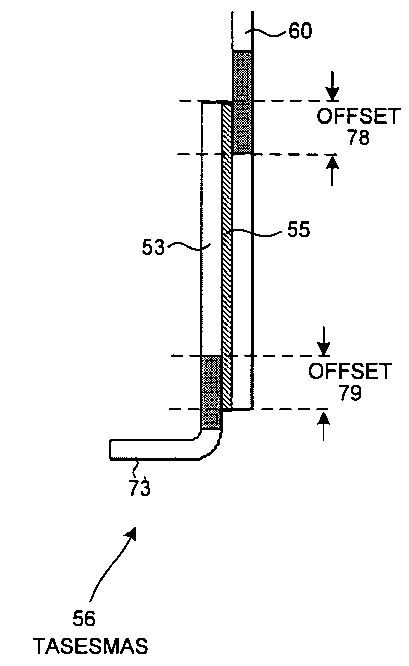
[0046]FIG. 6 is a cross-sectional diagram of an electrical connector 50 in accordance with one novel aspect. Connector 50 includes a connector body portion 51 and a plurality of temperature-activated self-extending surface mount attachment structures (TASESMAS). Each TASESMAS includes a self-adjusting surface mount attachment structure and an amount of a low melting-temperature metal. In the illustrated example, each self-adjusting surface mount attachment structure is an L-shaped strip of stamped metal. In the orientation of the illustration of FIG. 6, the bottom horizontally extending end portion of each strip is referred to as a “solder tail”.

[0047]FIG. 7 is an expanded view of a portion 52 of the structure of FIG. 6. Portion 52 includes two L-shaped self-adjusting surface mount attachment structures 53 and 54. The darker layer 55 of material is the amount of low melting-temperature metal (for example, solder) that along with self-adjusting surface mount attachment structure 53 f...


PUM

PropertyMeasurementUnit
lengthaaaaaaaaaa
thickaaaaaaaaaa
thickaaaaaaaaaa

Abstract

A surface mount component (for example, an electrical connector) includes a connector body portion and a plurality of temperature-activated self-extending surface mount attachment structures (TASESMAS). During a reflow solder process, amounts of solder within the connector melt. Surface and interfacial tensions of structures within the connector cause the TASESMAS structures to extend away from the connector body portion and toward an object (for example, a printed circuit board) to which the surface mount component is to be surface mount soldered. Each TASESMAS may self-extend a different amount to accommodate nonplanarities in the surface to which the component is to be surface mounted. When the component cools after reflow soldering, the amounts of solder solidify thereby fixing the TASESMAS structures in their extended positions.

Description

BACKGROUND INFORMATION[0001]FIG. 1 (Prior Art) is a cross-sectional diagram of a connector 1 that is to be surface mount soldered to a printed circuit board 2. The connector 1 includes a connector body portion 3 and a set of metal pins. The end of each metal pin is referred to as a “solder tail”. Solder tail 4, for example, is the end of metal pin 5. In order to surface mount connector 1 to printed circuit board 2, solder-wettable contact pads or traces on the upper surface of printed circuit board 2 are covered with amounts of solder paste 6. The contact pads or traces are not illustrated in FIG. 1. The amounts of solder paste may, for example, be approximately 0.18 millimeters thick. Connector 1 is then placed down onto the printed circuit board 2 so that the solder tails of connector 1 are forced down into the solder paste.[0002]FIG. 2 (Prior Art) is a cross-sectional diagram that shows connector 1 in place on the printed circuit board 2. An amount of solder paste is in contact w...

Claims


Application Information

Patent Timeline
Patent Type & Authority Patents(United States)
IPC IPC(8): H01R12/00
CPCH01R12/57H01R13/03H01R43/0256H05K3/3426Y10T29/4913H05K2201/10189H05K2201/10962H05K2203/306H05K2201/09136Y02P70/50
Inventor JEON, MYOUNGSOO
Owner CNPLUS
Why Eureka
Try Eureka